¶ pwm programming
PWM (Pulse Width Modulation) function is very common in embedded systems, it is the use of the microprocessor's digital outputs to control analog circuits is a very effective technique, widely used in many areas from measurement, communications to power control and conversion.
Rockchip PWM can support standard PWM interface programming under Linux.
The board leads a PWM for customized use, and the rest of the PWM for the screen backlight, has been exclusive to other drivers, can not be used for other functions.

You can check which pwm devices are on the board by the following command
rk3588_u:/ # find /sys -name "*pwmchip*"
find: '/sys/kernel/debug/pinctrl': loop detected
/sys/class/pwm/pwmchip2
/sys/class/pwm/pwmchip0
/sys/class/pwm/pwmchip3
/sys/class/pwm/pwmchip1
/sys/devices/platform/fd8b0020.pwm/pwm/pwmchip2
/sys/devices/platform/fd8b0010.pwm/pwm/pwmchip1
/sys/devices/platform/febf0030.pwm/pwm/pwmchip3
/sys/devices/platform/pwm-gpio/pwm/pwmchip0
By querying the device tree, we can know that fd8b0010 fd8b0020 febf0030 is the register header address of pwm1 pwm2 pwm15, so pwmchip3 is the node of pwm15.
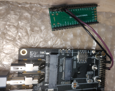
The following is a simple logic analyzer to capture the waveform of this pwm, wired as follows
By default, sysfs nodes require the root user to operate. If you want to use other user, you need to use adb or shell to execute the following commands
su
# Setting up pwm for userspace use
echo 0 > /sys/class/pwm/pwmchip3/export
# Give 777 permissions
chmod -R 777 /sys/class/pwm/pwmchip3
chmod 777 /sys/class/pwm/pwmchip3/pwm0/*
¶ Command Line Operation of PWM
Set the period of PWM, the unit is ns.
echo 10000 > /sys/class/pwm/pwmchip3/pwm0/period
Set the duty cycle, if the output polarity is normal, this parameter specifies the duration of high level in one cycle of PWM wave, unit ns
echo 5000 > /sys/class/pwm/pwmchip3/pwm0/duty_cycle
polarity parameter is used to specify the output polarity, i.e., whether the PWM output is inverted or not
echo normal > /sys/class/pwm/pwmchip3/pwm0/polarity
Enable pwm channel output
echo 1 > /sys/class/pwm/pwmchip3/pwm0/enable
The result is as follows, you can see that the length of both high and low levels is 5us

¶ Android app operation PWM
JAVA interface code is as follows, here only need to use a simple read and write function can be
    public static void writeToFile(String fileName, String content) throws IOException {
        try (BufferedWriter writer = new BufferedWriter(new FileWriter(fileName))) {
            writer.write(content);
        }
    }

    public static String readFileToString(String fileName) throws IOException {
        if (Build.VERSION.SDK_INT >= Build.VERSION_CODES.O) {
            return new String(Files.readAllBytes(Paths.get(fileName)), StandardCharsets.UTF_8);
        }
        return null;
    }

    public static boolean isFileExists(String filePath) {
        if (filePath == null || filePath.isEmpty()) {
            return false;
        }
        File file = new File(filePath);
        return file.exists();
    }
On the basis of the app created in the previous section, add a button and a text box, press the button to output PWM, and press it again to stop the PWM output.
private boolean isPWMEnable = false;

        button6.setText("pwm enable");
        button6.setOnClickListener(new View.OnClickListener() {
            @Override
            public void onClick(View v) {
                textDisplay.setText("start pwm test... \n");

                if(!isFileExists("/sys/class/pwm/pwmchip3/pwm0/period")) {
                    textDisplay.append("pwm not export... \n");
                } else {
                    if(!isPWMEnable) {
                        isPWMEnable = true;
                        button6.setText("pwm disable");
                        try {
                            writeToFile("/sys/class/pwm/pwmchip3/pwm0/period","20000");
                            writeToFile("/sys/class/pwm/pwmchip3/pwm0/duty_cycle","6000");
                            writeToFile("/sys/class/pwm/pwmchip3/pwm0/polarity","normal");
                            writeToFile("/sys/class/pwm/pwmchip3/pwm0/enable","1");
                        } catch (IOException e) {
                            throw new RuntimeException(e);
                        }
                    } else {
                        isPWMEnable = false;
                        button6.setText("pwm enable");
                        try {
                            writeToFile("/sys/class/pwm/pwmchip3/pwm0/enable","0");
                        } catch (IOException e) {
                            throw new RuntimeException(e);
                        }
                    }


                }
            }
        });
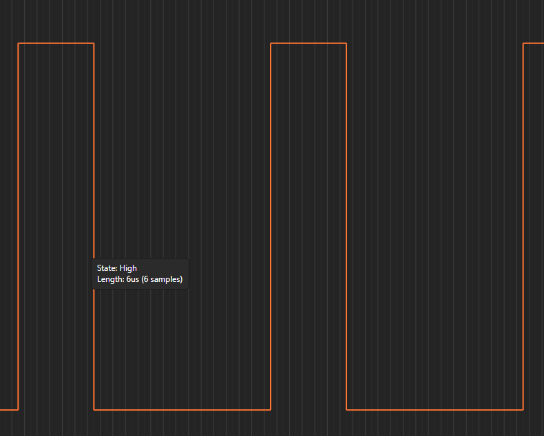
After pressing this button, you can see the PWM waveform, in which the high level time is 6us, low level time is 14us.