- ADC (Analog-to-Digital Converter) converts analog signals into digital signals and is commonly used in electronic devices such as audio, video processing, and sensor applications.
- The r1 development board is a 12-bit ADC.
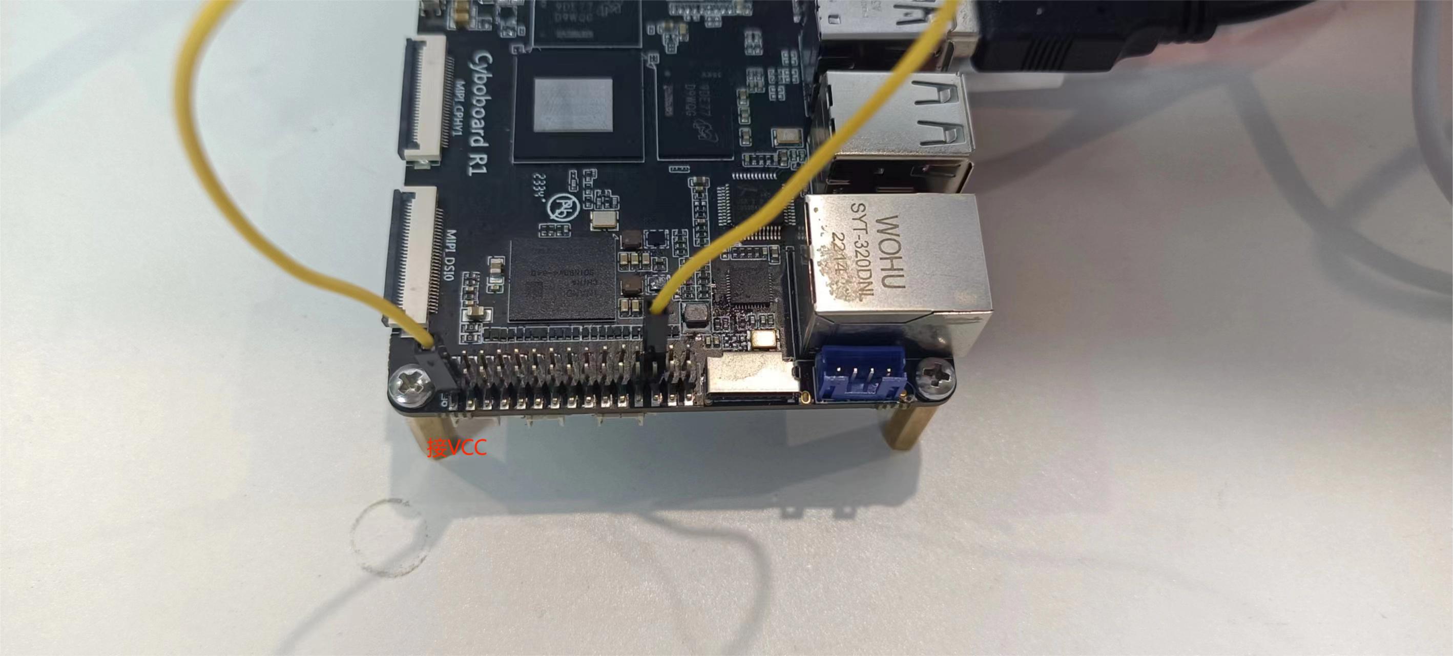
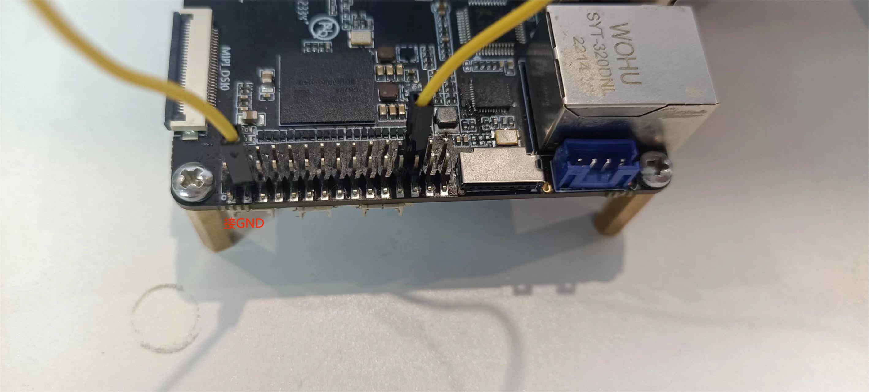
- The r1 development board has a total of two adc channels. Here, channel 4 is taken as an example.
- When testing, connect VCC first, then GND. (As shown below)
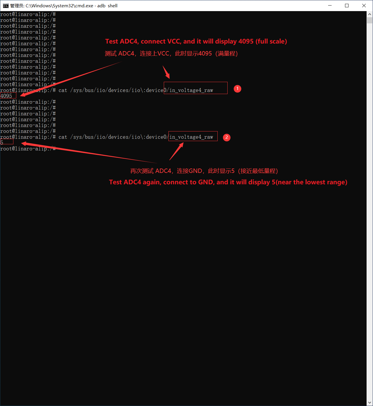
- Click Terminal--Enter the following command
cat /sys/bus/iio/devices/iio\:device0/in_voltage4_raw
- The first test is connected to vcc, and it should be full scale at this time; the second test is connected to gnd, and the output should be empty at this time.