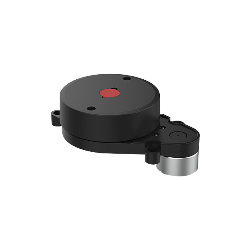
¶ LD20 Datasheet
¶ 1.Principle and system introduction
The LD20 consists mainly of a laser ranging core unit, a wireless power transmission unit, a wireless communication unit, an angle measuring unit, a motor drive unit and a mechanical housing.
The LD20 ranging core uses triangulation technology, which can measure 4000 times per second. Each time the distance is measured, the LD20 emits infrared laser light from a fixed angle, and the laser light is reflected to the receiving unit after encountering the target object. The distance is calculated through the triangular relationship formed by the laser, the target object and the receiving unit.
Once the distance data have been obtained, LD20 will combine the angle values measured by the angle measuring unit to form the point cloud data and then sends the point cloud data to an external interface via wireless communication unit. At the same time, the motor drive unit will drive the motor and control it to the specified speed through the PID algorithm closed-loop.
The diagram of the environmental scan formed by LD20 point cloud data is shown below:

¶ 2.Technical Parameters
¶ 2.1 Ranging accuracy
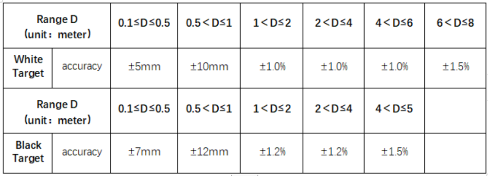
Ranging accuracy under normal temperature environment
Ranging accuracy under abnormal temperature /after/long time storage/after reliability test:
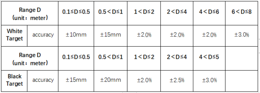
Remarks:
- The reflectivity of white target is 80%,black target is 4.0%: (Test results of C84-Ill reflectivity tester) 2.Range accuracy: each distance point is the average value of 30 consecutive data calculations collected from the horizontal ± 1° of the baffle center.
¶ 2.2.Performance parameters
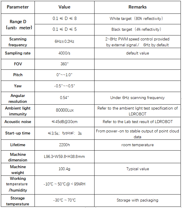
Remarks:
1.Test results of the above ranging accuracy parameters at room temperature: Ta=25 ℃. 2.Ambient light immunity performance parameter is obtained under the internal test laboratory.
Please refer to the ambient light immunity test method and test report for more detail.
3.Actual product weight may vary depending on configuration, manufacturing process and measurement method
¶ 2.3.Optical parameters

¶ 2.4.Electrical parameters

¶ 3.data interface
¶ 3.1. Communications and Interfaces
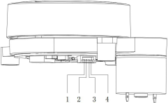
LD20 is connected via a ZH1.5T-4P 1.25mm connector for power supply and data reception.The interface definitions and parameter requirements are shown in the following diagram/table:
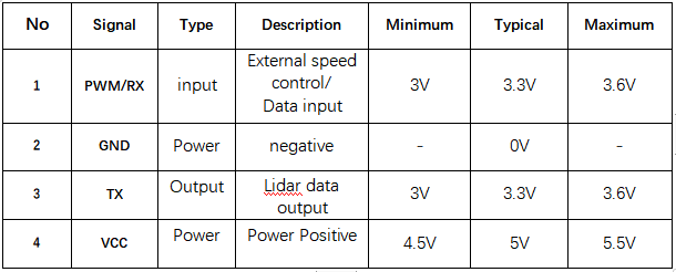
The data communication of LD20 adopts standard asynchronous serial port (UART) for one-way transmission, and its transmission parameters are shown in the table below:

¶ 3.2. Coordinate definition
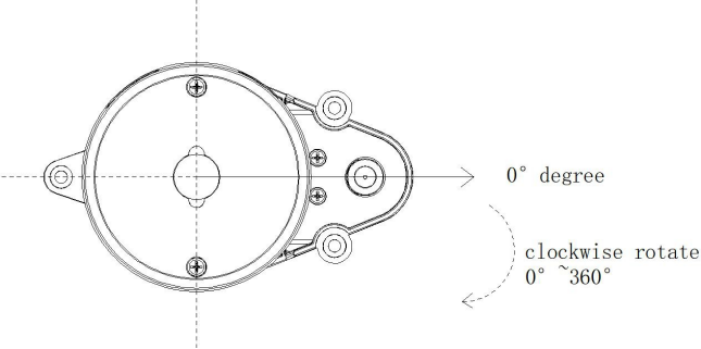
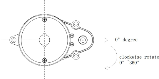
The LD20 use the left-handed coordinate system, the rotation center is he coordinate origin, the direction of the connection between the rotation center and the center of the driving wheel is zero degree direction, and the rotation angle increases in the clockwise direction .
Optical window and Product dimensions
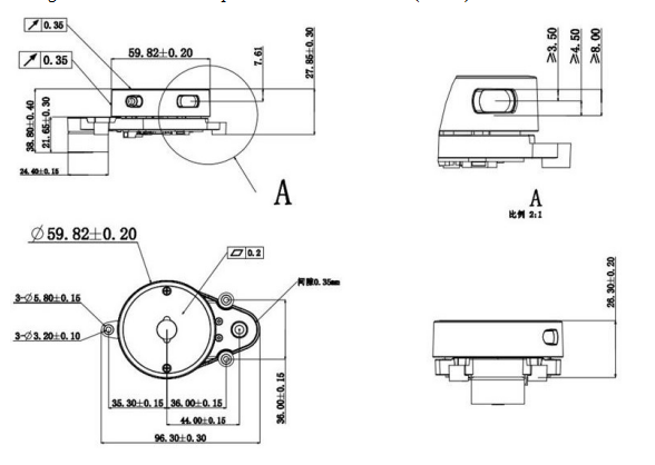
The laser emission and reception in the ranging unit of the LD20 requires an optical window, which needs to be exposed. Any block of this window by external systems will affect the ranging performance of the LIDAR to some extent.
The diagram below shows the optical window dimensions (in mm).
¶ LD20 Development Manual
¶ 1.communication protocol
¶ 1.1 Packet form
LD20 adopts one-way communication. After stable operation, it starts to send measurement data packets without any instruction. The following figure shows the format of measurement packets.

initial identifier: length 1 Byte, fixed value of 0 x54 said the start of a packet;
VerLen: length 1 Byte, three said frame type, is fixed to 1, low five measuring points, said a package is fixed for 12, fixing the Byte value of 0 x2c;
radar speed: length 2 Byte, the unit for degrees per second;
starting Angle: the length of the 2 Byte, the unit of 0.01 degrees;
data: a measurement data length is 3 bytes, detailed analysis, please see the next section;
end Angle: the length of the Byte, 2 units of 0.01 degrees;
timestamp: length 2 Byte, the unit for ms, 30000, 30000 to count;
CRC check: The checksum of all previous data;
The data structure reference is as follows:
#define POINT_PER_PACK 12
#define HEADER 0x54

typedef struct	 attribute ((packed)) { uint16_t distance;
uint8_t intensity;

} LidarPointStructDef;

typedef struct	 attribute ((packed)) {
uint8_ t  header;
uint8_ t  ver_ len;
uint16_ t  speed;
uint16 t   start angle;
LidarPointStructDef point[POINT_ PER_ PACK];
uint16_ t   end_ angle;
uint16_ t   timestamp;
uint8_ t   crc8;
)LiDARFrame TypeDef;
CRC check calculation method is as follows:
static const uint8_t CrcTable[256]
={ 0x00, 0x4d, 0x9a, 0xd7, 0x79, 0x34,
0xe3,
0xae, 0xf2, 0xbf, 0x68, 0x25, 0x8b, 0xc6, 0x11, 0x5c, 0xa9, 0xe4, 0x33,
0x7e, 0xd0, 0x9d, 0x4a, 0x07, 0x5b, 0x16, 0xc1, 0x8c, 0x22, 0x6f, 0xb8,
0xf5, 0x1f, 0x52, 0x85, 0xc8, 0x66, 0x2b, 0xfc, 0xb1, 0xed, 0xa0, 0x77,
0x3a, 0x94, 0xd9, 0x0e, 0x43, 0xb6, 0xfb, 0x2c, 0x61, 0xcf, 0x82, 0x55,
0x18, 0x44, 0x09, 0xde, 0x93, 0x3d, 0x70, 0xa7, 0xea, 0x3e, 0x73, 0xa4,
0xe9, 0x47, 0x0a, 0xdd, 0x90, 0xcc, 0x81, 0x56, 0x1b, 0xb5, 0xf8, 0x2f,
0x62, 0x97, 0xda, 0x0d, 0x40, 0xee, 0xa3, 0x74, 0x39, 0x65, 0x28, 0xff,
0xb2, 0x1c, 0x51, 0x86, 0xcb, 0x21, 0x6c, 0xbb, 0xf6, 0x58, 0x15, 0xc2,
0x5f, 0xf1, 0xbc, 0x6b, 0x26, 0x7a, 0x37, 0xe0, 0xad, 0x03, 0x4e, 0x99,
0xd4, 0x7c, 0x31, 0xe6, 0xab, 0x05, 0x48, 0x9f, 0xd2, 0x8e, 0xc3, 0x14,
0x59, 0xf7, 0xba, 0x6d, 0x20, 0xd5, 0x98, 0x4f, 0x02, 0xac, 0xe1, 0x36,
0x7b, 0x27, 0x6a, 0xbd, 0xf0, 0x5e, 0x13, 0xc4, 0x89, 0x63, 0x2e, 0xf9,
0xb4, 0x1a, 0x57, 0x80, 0xcd, 0x91, 0xdc, 0x0b, 0x46, 0xe8, 0xa5, 0x72,
0x3f, 0xca, 0x87, 0x50, 0x1d, 0xb3, 0xfe, 0x29, 0x64, 0x38, 0x75, 0xa2,
0xef, 0x41, 0x0c, 0xdb, 0x96, 0x42, 0x0f, 0xd8, 0x95, 0x3b, 0x76, 0xa1,
0xec, 0xb0, 0xfd, 0x2a, 0x67, 0xc9, 0x84, 0x53, 0x1e, 0xeb, 0xa6, 0x71,
0x3c, 0x92, 0xdf, 0x08, 0x45, 0x19, 0x54, 0x83, 0xce, 0x60, 0x2d, 0xfa,
0xb7, 0x5d, 0x10, 0xc7, 0x8a, 0x24, 0x69, 0xbe, 0xf3, 0xaf, 0xe2, 0x35,
0x78, 0xd6, 0x9b, 0x4c, 0x01, 0xf4, 0xb9, 0x6e, 0x23, 0x8d, 0xc0, 0x17,
0x5a, 0x06, 0x4b, 0x9c, 0xd1, 0x7f, 0x32, 0xe5, 0xa8
};

uint8_t CalCRC8(uint8_t *p, uint8_t len){ uint8_t crc = 0;
uint16_t i;

for (i = 0; i < len; i++){

crc = CrcTable[(crc ^ *p++) & 0xff];

}

return crc;

}
¶ 1.2 Measurement data analysis
Each measurement data point consists of a 2-byte distance value and a 1-byte confidence value, as shown in the figure below.

The unit of distance value is mm. The signal intensity value reflects the light reflection intensity, the higher the intensity, the larger the signal intensity value; The lower the intensity, the smaller the signal strength value.
The Angle value of each point is obtained by linear interpolation of the starting Angle and the ending Angle. The Angle calculation method is as follows:
step = (end_angle -- start_angle)/(len -- 1);
angle = start_angle + step*i;

len is the number of measurement points of a packet, and the value range of i is [0, len].
¶ 1.3 example
54 2C 68 08 AB 7E E0 00 E4 DC 00 E2 D9 00 E5 D5 00 E3 D3 00 E4 D0 00 E9 CD
00 E4 CA 00 E2 C7 00 E9 C5 00 E5 C2 00 E5 C0 00 E5 BE 82 3A 1A 50
We analyze it as follows:

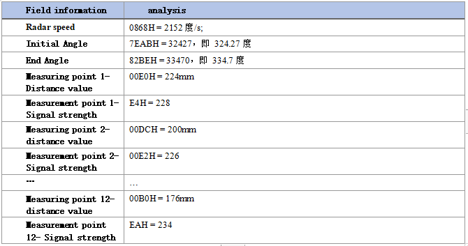
Due to the principle of trigonometric ranging, the above Angle value is uncorrected. See SDK for the detailed revision processSource transform.cpp in the Transform() function.
¶ 2.coordinate system
LD20 uses the left hand coordinate system, the center of rotation is the origin of coordinates, the right front of the sensor is defined as the zero degree direction, and the rotation Angle increases along the clockwise direction, as shown in the figure below.
¶ 3.Develop the instructions for the suite
¶ 3.1. Evaluate the use of tools
¶ 3.1.1Hardware wire connection and description
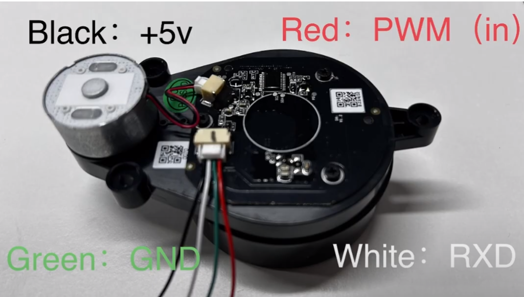
- Product, wire and USB adapter board, as shown in the figure below:
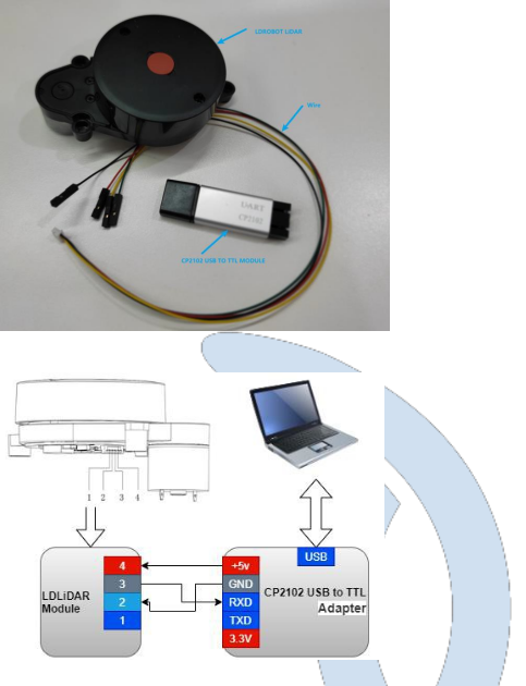
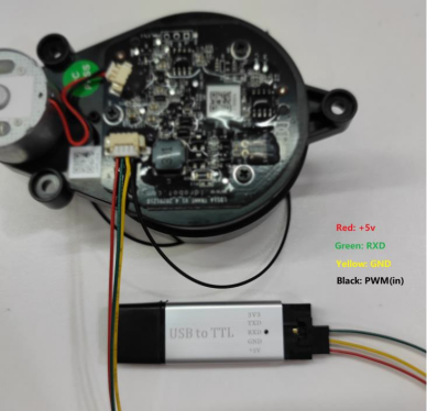
Tips: Different batches of wire may result in different wire sequences. Refer to the correct wire sequence for wiring.
¶ 3.1.2. Installing the driver in windows
When evaluating our products under windows, it is necessary to install the serial port driver of USB adapter board, because CP2102 USB to serial port signal chip is adopted in the USB adapter board provided by our company. Its drivers can be downloaded from the official Silicon Labs website:
https://www.silabs.com/developers/usb-to-uart-bridge-vcp-drivers
Or download it from our open source repository:
https://drive.google.com/file/d/14lkdtn6cF0aw0EFbKhwYbB0j7faX-U-9/view?usp=sharing
Decompress the CP210x_Universal_Windows_Driver driver package, run the exe file in the driver installation package directory, and select X86(32-bit) or X64(64-bit) based on the Windows OS version.
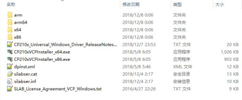
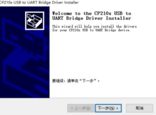
Double-click the exe file and follow the prompts to install it.
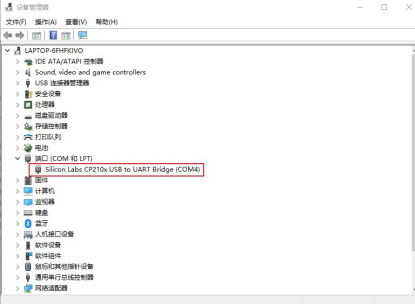
After the installation is complete, connect the USB adapter board in the development kit to the computer. You can right-click "My Computer" and choose "Properties". In the open "System" interface, select "Device Manager" from the left menu to enter the Device Manager and expand "Port". That is, the driver is installed successfully. The following figure shows COM4.
¶ 3.1.3. Evaluate the use of host computer software ld_desktop under windows
Our company provides point cloud visualization software ld_desktop for real-time scanning of this product. Developers can use this software to visually observe the scanning effect map of this product. Before using this software, ensure that the driver program of USB switching board of this product has been installed successfully, and connect this product with USB port of PC in Windows system. Then double-click LD_Deskdesktop.exe, select the corresponding product model and port number, and click the startup point cloud refresh button, as shown in the following figure.
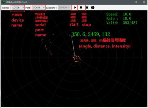
In the figure above, Speed represents the laser radar scanning frequency (unit: Hz). Rate indicates the rate of lidar packet parsing; Valid Indicates the valid point of the lidar measurement circle.
The ld_desktop software binary package can be downloaded from our open source repository:
https://drive.google.com/file/d/14lkdtn6cF0aw0EFbKhwYbB0j7faX-U-9/view?usp=sharing
¶ 3.2 Product 3D model file
The company provides 3D model files of this product in stp format to developers, which can be downloaded by visiting our open source warehouse:
https://drive.google.com/file/d/18faoB64QVZNB6B6lRrc0T2Hhr1QzJRBa/view?usp=sharing
¶ 3.3. Ros-based operations in Linux
¶ 3.3.1.ROS Environment introduction and installation
ROS (Robot Operating System, "ROS" for short) is an open source meta-operating system for robots and middleware built on top of the Linux system. It provides the services expected of an operating system, including hardware abstraction, underlying device control, implementation of common functions, interprocess messaging, and package management. It also provides the tools and library functions needed to get, compile, write, and run code across computers. ROS each version of the installation steps, please refer to the ROS's official website: http://wiki.ros.org/ROS/Installation
The ROS function pack of this product supports the following version environments:
ROS Kinetic(Ubuntu16.04);
ROS Melodic(Ubuntu18.04);
ROS Noetic(Ubuntu20.04).
¶ 3.3.2.Obtain the source code of the feature pack
The source code of ROS function pack of this product is hosted on Github and Gitee repositories. You can download the source code of master or main branch by accessing the repository network link, or download it by git tool.
- Warehouse website address
https://drive.google.com/file/d/1BLg166GuwafHsBuxaj0KSA7VryfGyq7d/view?usp=sharing
git tool download operation
# First open the terminal interface, you can use the ctrl+alt+t shortcut
If you do not have git installed on your Ubuntu operating system, you can install Git using the following methods:
$ sudo apt-get install git
Download the ROS feature pack.
$ cd ~
$ mkdir -p ldlidar_ros_ws/src
$ cd ~/ldlidar_ros_ws/src
$ git clone https://gitee.com/ldrobotSensorTeam/ldlidar_sl_ros.git
# or
$ git clone https://github.com/ldrobotSensorTeam/ldlidar_sl_ros.git
¶ 3.3.3. Setting device Permissions
First, the radar is connected to our switch module (CP2102 serial port switch module), and the module is connected to the computer. Then, open a terminal in ubuntu and type ls /dev/ttyUSB* to check whether the serial port device is connected. If a serial port device is detected, run the sudo chmod 777 /dev/ttyusb * command to grant the highest read/write permission to the file owner, group, and other users, as shown in the following figure.

Finally, change the port_name value in the ld14.launch file in the ~/ldldiar_ros_ws/src/ldlidar_sl_ros/launch/ directory. Take /dev/ttyusb0 as an example.
$ nano ~/ldlidar_ros_ws/src/ldldiar_sl_ros/launch/ld14.launch
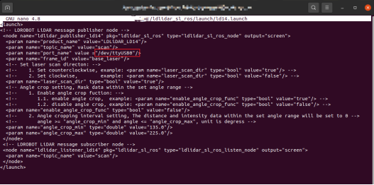
Linux nano editor: Ctrl + O to save the edit file; Ctrl + X to exit the editing screen.
¶ 3.3.4.Build and environment settings
- Compile and build product function packs with catkin compilation system:
$ cd ~/ldlidar_ros_ws
$ catkin_make
- Function pack environment variable setting:
After the compilation is complete, you need to add the related files generated by the compilation to the environment variables so that the ROS environment can be identified. Run the following command. The command is used to temporarily add environment variables to the terminal, which means that you need to run the following command again if you restart a new terminal.
$ cd ~/ldlidar_ros_ws
$ source devel/setup.bash
To permanently remove the need to run the preceding command to add environment variables after restarting the terminal, perform the following operations.
$ echo “source ~/ldlidar_ros_ws/devel/setup.bash” >> ~/.bashrc
$ source ~/.bashrc
¶ 3.3.5. Run the program
Use roslaunch tool to start the radar node and execute the following command.
$ roslaunch ldlidar_sl_ros ld14.launch
¶ 3.3.6.Rviz displays radar point cloud
Rviz is a 3D visualization tool within the ROS framework that allows radar data to be displayed. in
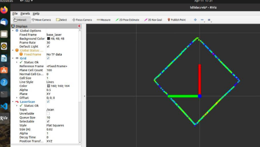
After roslaunch successfully runs the radar node, open a new terminal (Ctrl+Alt+T) and enter the following command:
$ rosrun rviz rviz
After the interface is started, click file->open->Config on the menu bar of the interface, and then select:
~/ldlidar_ros_ws/src/ldlidar_sl_ros/rviz/ directory ldlidar.rviz to open the configuration file
After ldlidar.rviz, click on LaserScan Topic and select /scan.
Since the point cloud data of our radar products follow the left-handed coordinate system, while the radar point cloud data displayed by Rviz follow the right-handed coordinate system, we carried out the coordinate system transformation of the product point cloud data in the function package source toLaserScan function, so that it can normally display the point cloud in Rviz.
In addition, there is a certain compatibility problem with the Rviz configuration file between different ROS versions. If you open the ldlidar.rviz file and set relevant parameters, you still cannot view the lidar point cloud or the Rviz tool crashes. You can solve this problem by creating another Rviz configuration file that mimics the Settings of ldlidar.rviz.
¶ 3.4. Ros2-based operations in Linux
¶ 3.4.1.ROS2 Environment Introduction and Installation
ROS (Robot Operating System, "ROS" for short) is an open source meta-operating system for robots and middleware built on top of the Linux system. It provides the services expected of an operating system, including hardware abstraction, underlying device control, implementation of common functions, interprocess messaging, and package management. It also provides the tools and library functions needed to get, compile, write, and run code across computers. Since the
Much has changed in robotics and the ROS community since ROS was launched in 2007. The ROS2 project aims to adapt to these changes, taking advantage of the strengths of ROS1 and improving on the weaknesses. For details about how to install ROS2, see
ROS2 official website: https://docs.ros.org/en/foxy/Installation.html
The ROS2 function package of this product can be used in the ROS2 Foxy(Ubuntu20.04) environment.
¶ 3.4.2. Obtain the source code of the feature pack
The source code of ROS2 function pack of this product is hosted on the repositories of Github and Gitee. You can download the source code of master or main branch by accessing the network link of the repositories, or download it by git tool.
- Warehouse website address
https://drive.google.com/file/d/1OA6fNhxpOdQQVz0E5GgcRk54EqZ_jPcJ/view?usp=sharing
2)git tool download operation
# First open the terminal interface, you can use the ctrl+alt+t shortcut
If you do not have git installed on your Ubuntu operating system, you can install Git using the following methods:
$ sudo apt-get install git
# ROS2
$ cd ~
$ mkdir -p ldlidar_ros2_ws/src
$ cd ~/ldlidar_ros2_ws/src
$ git clone https://gitee.com/ldrobotSensorTeam/ldlidar_sl_ros2.git
# or
$ git clone https://github.com/ldrobotSensorTeam/ldlidar_sl_ros2.git
¶ 3.4.3. Setting device Permissions
First, the radar is connected to our switch module (CP2102 serial port switch module), and the module is connected to the computer. Then, open a terminal in ubuntu and type ls /dev/ttyUSB* to check whether the serial port device is connected. If a serial port device is detected, run the sudo chmod 777 /dev/ttyusb * command to grant the highest read/write permission to the file owner, group, and other users, as shown in the following figure.

Finally, change the port_name value in the ld14.launch.py file in the ~/ldldiar_ros2_ws/src/ldlidar_sl_ros2/launch/ directory. Take /dev/ttyusb0 as an example.
$ nano ~/ldlidar_ros2_ws/src/ldldiar_sl_ros2/launch/ld14.launch.py
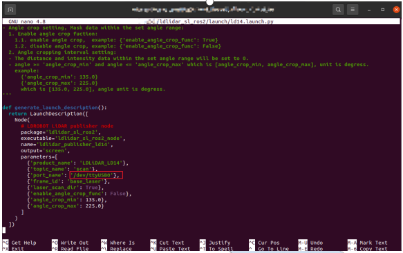
Linux nano editor: Ctrl + O to save the edit file; Ctrl + X to exit the editing screen.
¶ 3.4.4 Compilation and environment setup
1.Compile and build product feature packs using colcon compilation system
$ cd ~/ldlidar_ros2_ws
$ colcon build
2.Feature pack environment variable Settings:
After the compilation is complete, related files generated by compilation need to be added to environment variables so that ROS2 environment can be identified. Run the following command, which is to temporarily add environment variables to the terminal, which means that if you reopen a new terminal, you need to run the following command again.
$ cd ~/ldlidar_ros2_ws
$ source install/setup.bash
To permanently remove the need to run the preceding command to add environment variables after restarting the terminal, perform the following operations.
$ echo “source ~/ldlidar_ros2_ws/install/setup.bash” >> ~/.bashrc
$ source ~/.bashrc
¶ 3.4.5. Run the program
Use ros2 launch tool to start the radar node and execute the following command.
$ ros2 launch ldlidar_sl_ros2 ld14.launch.py
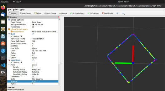
¶ 3.4.6.Rviz2 Displays radar point cloud
Rviz2 is a 3D visualization tool within the ROS2 framework where radar data can be displayed. in
After ros2 launch successfully runs the radar node, open a new terminal (Ctrl+Alt+T) and enter the following command:
$ rviz2
After the interface is started, click file->open->Config on the menu bar of the interface, and then select:
~/ldlidar_ros2_ws/src/ldlidar_sl_ros2/rviz2/ directory ldlidar.rviz file, open the configuration file ldlidar.rviz, click LaserScan Topic and select /scan.
Since the point cloud data of our radar products follow the left-handed coordinate system, while the radar point cloud data displayed by Rviz2 follow the right-handed coordinate system, we carried out coordinate transformation of the product point cloud data in the function package source toLaserScan function, so that it can normally display point cloud in Rviz2.
¶ 3.5. SDK Usage in Linux
¶ 3.5.1. Obtain the SDK source code
The Linux SDK source code of this product is hosted on Github and Gitee warehouses. You can download the source code of master or main branch by accessing the warehouse network link, or download it by git tool.
- Warehouse website address
https://drive.google.com/file/d/1GxOehO27rCt9JUXyA8E568rC4hKpHqi8/view?usp=sharing
2)git tool download operation
# First open the terminal interface, you can use the ctrl+alt+t shortcut
If you do not have git installed on your Ubuntu operating system, you can install Git using the following methods:
$ sudo apt-get install git

# Download the source code of the ROS2 feature pack:
$ cd ~
$ mkdir	ldlidar_ws
$ cd ~/ldlidar_ws
$ git clone https://gitee.com/ldrobotSensorTeam/ldlidar_sl_sdk.git
# or
$ git clone https://github.com/ldrobotSensorTeam/ldlidar_sl_sdk.git
¶ 3.5.2. Setting Device Permissions
First, the radar is connected to our switch module (CP2102 serial port switch module), and the module is connected to the computer. Then, open a terminal in ubuntu and type ls /dev/ttyUSB* to check whether the serial port device is connected. If a serial port device is detected, run the sudo chmod 777 /dev/ttyusb * command to grant the highest read/write permission to the file owner, group, and other users, as shown in the following figure.

¶ 3.5.3. Compile the source code
The source code is coded in C++11 and C language C99. The source code is compiled and constructed using tools such as CMake, GNU-make, and GCC. If you do not have the above tools installed on the Ubuntu system, run the following command to complete the installation.
$ sudo apt-get install build-essential cmake
If the preceding tools already exist in the system, perform the following operations.
$ cd ~/ldlidar_ws/ldlidar_sl_sdk
··
$ mkdir build	# If the build folder does not exist in the ldlidar_sl_sdk directory, create one
$ cd build
$ cmake ../
$ make
¶ 3.5.4. Run the program
$ cd ~/ldlidar_ws/ldlidar_sl_sdk/build

$ ./ldlidar_sl	LD14	<serial_number>

#  such as ./ldlidar_sl	LD14	/dev/ttyUSB0
¶ 4. Optical window and mechanical dimensions
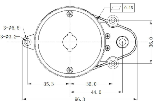
The laser transmitting and receiving in the ranging unit of LD20 requires an optical window, which needs to be exposed in the structure. The partial occlusion of the window by the external system will affect the ranging performance of LD20 to a certain extent. The following figure shows the optical window size (unit:mm). The overall dimensional tolerance is +0.3/-0.3mm.
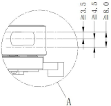
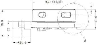
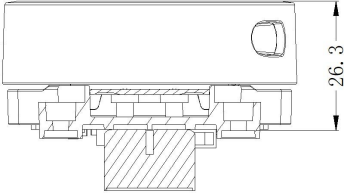
Other installation dimensions are shown in the following figure (unit: mm) :
¶ 5. Safety and application scope
 LD20 uses low-power infrared laser as the emission source, so it can ensure the safety of humans and pets. At present, this product has passed the Class I laser safety standard. LD20 complies with 21 CFR 1040.10 and 1040.11 except for deviations from Laser Circular No. 50 of 24 June 2007. Note: Adjusting
or modifying this product may result in dangerous radiation exposure.
¶ About us
Web:https://www.youyeetoo.com/
Forum:https://forum.youyeetoo.com/
amazon: https://www.amazon.com/youyeetoo
blog: https://youyeetoo.com/blog/
[cn web]:https://youyeetoo.cn/
aliexpress:https://smartfire.aliexpress.com/store/1100924668
Customized service:peter@youyeetoo.com