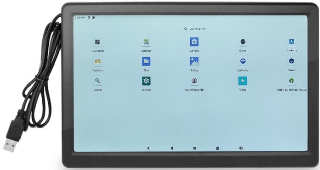
¶ HDMI screen
- By default, the project has enabled both HDMI and MiPI displays, which will cause HDMI to default to the resolution configured by MiPI. Enable route_dsi0 and DSI0, as shown in the following figure:
&route_dsi0 {
    status = "okay";
};

&dsi0 {
    status = "okay";

     dsi0_panel: panel@0 {
   .....
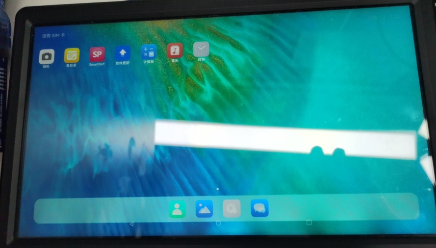
- Display effect:
¶ 7-inch MIPI screen
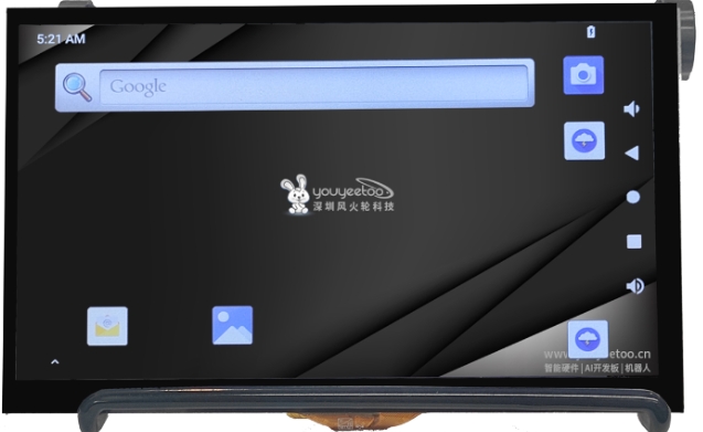
YYT-MIPI7LCD2203 is a 5-point capacitive touch, 7-inch color TFT-LCD module. This module consists of the following parts: TFT LCD panel, driver circuit, 5-point capacitive touch, and backlight.
Among them, the 5-point capacitive touch has 26 driving channels and 14 sensing channels, which can meet higher touch accuracy requirements. It can simultaneously recognize the real-time accurate position, movement trajectory, and touch area of 5 touch points. And according to the main control requirements, read the touch information of the corresponding points.
YY3568 provides two DSI interfaces, namely DSI0 and DSI1. Let's describe the configuration of DSI1 below.
We need to control some pins to light up the 7-inch MIPI screen. The hardware schematic of the screen is as follows:
- Backlight pin: LCD1-BL_PWM5
- Backlight enable pin: GPO3A_A5
- Enable pin: GPO4-D2
- Reset pin: GPO3A_A2
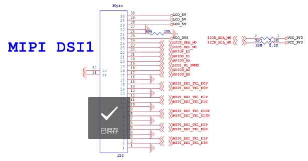
YYT-MIPI7LCD2203 Driver Device Tree Configuration rk3568-vp1-mipi-dsi1-1024x768.dtsi
We need to update the DSI1 node based on the configuration of YYT-MIPI7LCD2203 screen:
- Screen firmware parameters: panel in sequence
- Screen display parameter: disp_timings1
- Screen enable pin: enable gpios
- Screen reset pin: reset gpios
&dsi1 {
    status = "okay";
    dsi1_panel: panel@0 {
        status = "okay";
        compatible = "simple-panel-dsi";
        reg = <0>;
        backlight = <&backlight1>;

        enable-gpios = <&gpio4 RK_PD2 GPIO_ACTIVE_LOW>;
        reset-gpios = <&gpio3 RK_PA2 GPIO_ACTIVE_LOW>;
        reset-delay-ms = <60>;
        enable-delay-ms = <60>;
        prepare-delay-ms = <60>;
        unprepare-delay-ms = <60>;
        disable-delay-ms = <60>;
        dsi,flags = <(MIPI_DSI_MODE_VIDEO | MIPI_DSI_MODE_VIDEO_BURST |
            MIPI_DSI_MODE_LPM | MIPI_DSI_MODE_EOT_PACKET)>;
        dsi,format = <MIPI_DSI_FMT_RGB888>;
        dsi,lanes  = <4>;
        panel-init-sequence = [
            15 00 02 80 ac
            15 00 02 81 b8
            15 00 02 82 09
            15 00 02 83 78
            15 00 02 84 7f
            15 00 02 85 bb
            15 00 02 86 70
        ];

        panel-exit-sequence = [
            05 00 01 28
            05 00 01 10
        ];

        disp_timings1: display-timings {
            native-mode = <&dsi1_timing0>;
            dsi1_timing0: timing0 {
                clock-frequency = <65000000>;
                hactive = <1024>;
                vactive = <600>;
                hfront-porch = <160>;
                hback-porch = <160>;
                hsync-len = <10>;
                vfront-porch = <12>;
                vsync-len = <1>;
                vback-porch = <23>;
                hsync-active = <0>;
                vsync-active = <0>;
                de-active = <1>;
                pixelclk-active = <0>;
            };
        };

        ports {
            #address-cells = <1>;
            #size-cells = <0>;

            port@0 {
                reg = <0>;
                panel_in_dsi1: endpoint {
                    remote-endpoint = <&dsi1_out_panel>;
                };
            };
        };
    };

    ports {
        #address-cells = <1>;
        #size-cells = <0>;

        port@1 {
            reg = <1>;
            dsi1_out_panel: endpoint {
                remote-endpoint = <&panel_in_dsi1>;
            };
        };
    };

};
Screen backlight configuration:
- Backlight enable pin: enable gpios
- Enable backlight adjustment pwm: pwm5
&backlight1 {
    status = "okay";
    enable-gpios = <&gpio3 RK_PA5 GPIO_ACTIVE_HIGH>;
};

&pwm5 {
    status = "okay";
};
Set the output screen output port to vp1:
&route_dsi1 {
    status = "okay";
    connect = <&vp1_out_dsi1>;
};
- Display effect:

¶ Touch driven
From the schematic diagram, the touch chip of MiPi DSI1 screen is connected to i2C5, and the touch chip adopts GT911 chip. The parameters are as follows:
- The i2c address is 0x5d
- Screen resolution: 1024 * 600
- Interrupt pin: GPO0-C1
- Reset pin: GPO3-A0
&i2c5{
    status = "okay";
    gt9xx: gt9xx@5d {
        compatible = "goodix,gt9xx";
        reg = <0x5d>;
        touch-gpio = <&gpio0 RK_PC1 IRQ_TYPE_EDGE_RISING>;
        reset-gpio = <&gpio3 RK_PA0 GPIO_ACTIVE_LOW>;
        max-x = <1024>;
        max-y = <600>;
        tp-size = <911>;
        pinctrl-names = "default";
        pinctrl-0 = <&touch_gpio>;
        //tp-supply = <&vcc_io>;
        status = "okay";
    };
};

&pinctrl {
    touch {
        touch_gpio: touch-gpio {
            rockchip,pins =
                <0 RK_PC1 RK_FUNC_GPIO &pcfg_pull_up>,
                <3 RK_PA0 RK_FUNC_GPIO &pcfg_pull_none>;
        };
    };
};
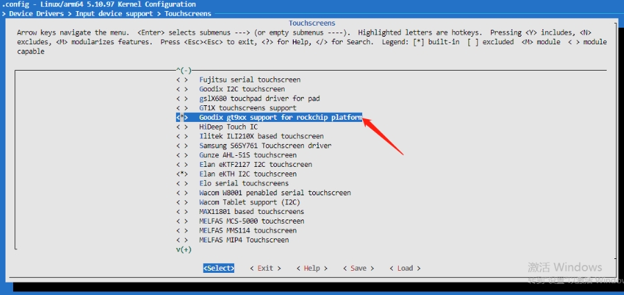
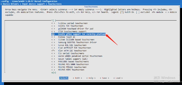
Open the driver of gt911 through menuconfig:
  │   Location:                                                                                                                                                │
  │     -> Device Drivers                                                                                                                                      │
  │       -> Input device support                                                                                                                              │
  │         -> Generic input layer (needed for keyboard, mouse, ...) (INPUT [=y])                                                                              │
  │           -> Touchscreens (INPUT_TOUCHSCREEN [=y])
¶ 11.6-inch EDP screen
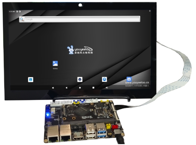
Youyetoo EDP screen with a 5-point capacitive touch and 11.6-inch color TFT-LCD. Featuring FHD (Full HD) resolution (1920 horizontal x 1080 vertical pixel array),
It can display 16.7M (16.7 million) colors, approaching the limit of human eye resolution. It has rich display colors, good layering, natural color transitions, and good color expression,
Advantages such as delicate screen. And the screen weighs only 96.6g.
We need to control some pins to light up the 11.6-inch EDP screen. The hardware schematic of the screen is as follows:
- Backlight pin: LCD1-BL_PWM14
- Backlight enable pin: GPO1_A4
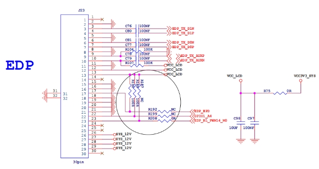
Device tree configuration rk3568-vp1-edp-1080p.dtsi for YYT-MIPI7LCD2203 driver
We need to update the DSI1 node based on the configuration of YYT-MIPI7LCD2203 screen:
- Screen firmware parameters: panel in sequence
- Screen display parameters: display limits
- Screen enable pin: enable gpios
- Screen reset pin: reset gpios
edp_panel {
        compatible = "simple-panel";
        backlight = <&backlight>;
        //power-supply = <&vcc3v3_lcd0_n>;
        prepare-delay-ms = <120>;
        enable-delay-ms = <120>;
        unprepare-delay-ms = <120>;
        disable-delay-ms = <120>;

        display-timings {
            native-mode = <&edp_timing>;

            edp_timing: timing0 {
                clock-frequency = <138500000>;
                hactive = <1920>;
                vactive = <1080>;
                hfront-porch = <64>;
                hsync-len = <32>;
                hback-porch = <64>;
                vfront-porch = <12>;
                vsync-len = <7>;
                vback-porch = <12>;
                hsync-active = <0>;
                vsync-active = <0>;
                de-active = <0>;
                pixelclk-active = <0>;
            };
        };

        port {
            panel_in_edp: endpoint {
                remote-endpoint = <&edp_out_panel>;
            };
        };
    };

&edp {
    status = "okay";
    force-hpd;

    ports {
        port@1 {
            reg = <1>;

            edp_out_panel: endpoint {
                remote-endpoint = <&panel_in_edp>;
            };
        };
    };
};
Screen backlight configuration:
- Backlight enable pin: enable gpios
- Enable backlight adjustment pwm: pwm14
&backlight {
    status = "okay";
    pwms = <&pwm14 0 25000 0>;
    enable-gpios = <&gpio1 RK_PA4 GPIO_ACTIVE_HIGH>;
};

&pwm14 {
    status = "okay";
};
Set the output screen output port to vp1:
&route_edp {
    status = "okay";
    connect = <&vp1_out_edp>;
};
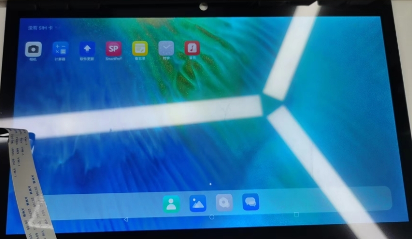
- Display result:
##Touch driven
From the schematic diagram, it can be seen that the touch chip of the EDP screen is connected to i2c1, and the touch chip uses the gt911 chip with the following parameters:
- The i2c address is 0x5d
- Screen resolution: 1920 * 1080
- Interrupt pin: GPO0-B7
- Reset pin: GPO3-A6
&i2c1 {
    status = "okay";
    gt9xx: gt9xx@5d {
        compatible = "goodix,gt9xx";
        reg = <0x5d>;
        touch-gpio = <&gpio0 RK_PB7 IRQ_TYPE_EDGE_RISING>;
        reset-gpio = <&gpio0 RK_PA6 GPIO_ACTIVE_LOW>;
        max-x = <1920>;
        max-y = <1080>;
        tp-size = <928>;
        pinctrl-names = "default";
        pinctrl-0 = <&touch_gpio>;
        //tp-supply = <&vcc_io>;
        status = "okay";
    };
};

&pinctrl {
    touch {
        touch_gpio: touch-gpio {
            rockchip,pins =
                <0 RK_PB7 RK_FUNC_GPIO &pcfg_pull_up>,
                <0 RK_PA6 RK_FUNC_GPIO &pcfg_pull_none>;
        };
    };
};
Open the driver of gt911 through menuconfig:
  │   Location:                                                                                                                                                │
  │     -> Device Drivers                                                                                                                                      │
  │       -> Input device support                                                                                                                              │
  │         -> Generic input layer (needed for keyboard, mouse, ...) (INPUT [=y])                                                                              │
  │           -> Touchscreens (INPUT_TOUCHSCREEN [=y])
