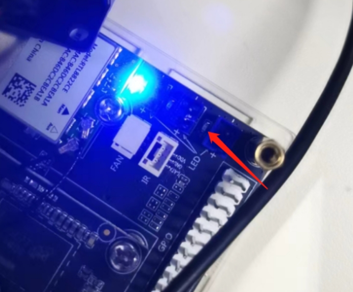
¶ RTC
From the schematic diagram, it can be seen that yy3568 is equipped with an RTC chip AT8563, which is hung on I2C5 and interrupts the GPIO 0-D3 pin, but can output a clock signal of 32.768kHz.
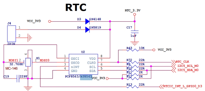
AT8563 is a real-time clock chip used to provide accurate time and date information. It is a low-power device commonly used in fields such as embedded systems, electronic devices, and computers. AT8563 can be connected to the main control chip or microprocessor through an I2C interface, track time through an internal crystal oscillator, and provide accurate clock functionality. It is commonly used for recording event timestamps, timing, alarm functions, and system power management applications.
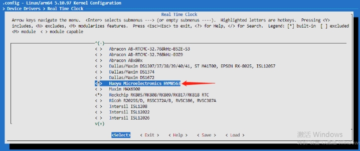
AT8563 and HYM8563 are completely replaceable, so when we adapt the driver, we directly use HYM8563 driver
¶ AT8563 hardware interface description:
- I2C Address: 0x51
- Interrupt pin: GPO0-D3
- CLKOUT pin: RTC_CLK
- I2C bus number: I2C5
¶ AT8563 Device Tree
&i2c5 {
    status = "okay";

    hym8563: hym8563@51 {
        compatible = "haoyu,hym8563";
        reg = <0x51>;
        pinctrl-names = "default";
        pinctrl-0 = <&rtc_int>;

        interrupt-parent = <&gpio0>;
        interrupts = <RK_PD3 IRQ_TYPE_LEVEL_LOW>;
    };
};
¶ AT8563 driver configuration
Open VNet RTC_SRV_SYM8563 through menuconfig
¶ AT8563 verification
After completing the above configuration, you can see the rtcN under /sys/class/rtc/.

AT8563 is registered in RTC1.

¶ AT8563 synchronization time
Read RTC clock through hwclock - r - f/dev/rtc1
If the chip does not synchronize the time, the driver will prompt: No valid clock/calendar values available

Synchronize time through hwclock - w - f/dev/rtc1 and write it to RTC
Read the RTC clock again through hwclock - r - f/dev/rtc1 to obtain the corresponding clock

¶ LED
The main functions of the LED subsystem in the Linux kernel are:
- Create different file nodes for each device in/sys/class/les for operating LEDs
- Abstract all the basic operations of lights, set on/off, light intensity, flashing, etc
YY3568 is connected to two blue LED lights, namely GPIO3A_A4 and GPIO02_S2, as shown in the following figure:
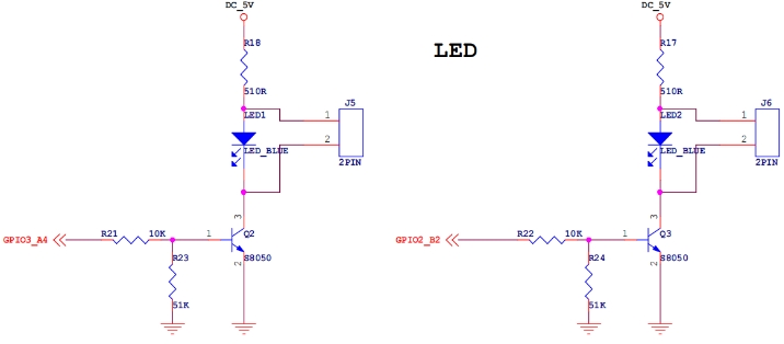
We will name two blue LEDs as blue1 and blue2.
¶ LED light equipment tree configuration
Add corresponding LED light nodes, compatible with gpio LEDs. Mount two LEDs in the node, labeled as blue1 and blue2 respectively:
gpio_leds: gpio-leds {
        compatible = "gpio-leds";
        led@1 {
            gpios = <&gpio3 RK_PA4 GPIO_ACTIVE_HIGH>;
            label = "blue1"; // Blue1
            retain-state-suspended;
        };

        led@2 {
            gpios = <&gpio2 RK_PB2 GPIO_ACTIVE_HIGH>;
            label = "blue2"; // Blue2
            retain-state-suspended;
        };
    };
Add corresponding LED light pin initialization configuration:
    leds_gpio: leds-gpio {
        rockchip,pins =
            <3 RK_PA4 RK_FUNC_GPIO &pcfg_pull_up>,
            <2 RK_PB2 RK_FUNC_GPIO &pcfg_pull_up>;
    };
¶ LED menuconfig configuration
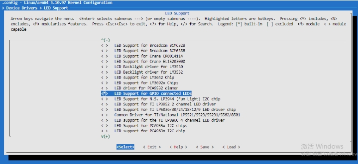
The configuration options are located as follows:
  │   Location:                                                                                                                                                │
  │     -> Device Drivers                                                                                                                                      │
  │       -> LED Support (NEW_LEDS [=y])
¶ Command line operation LED
After completing the above operations, compile and burn, and the corresponding file nodes can be generated in /sys/class/eds:

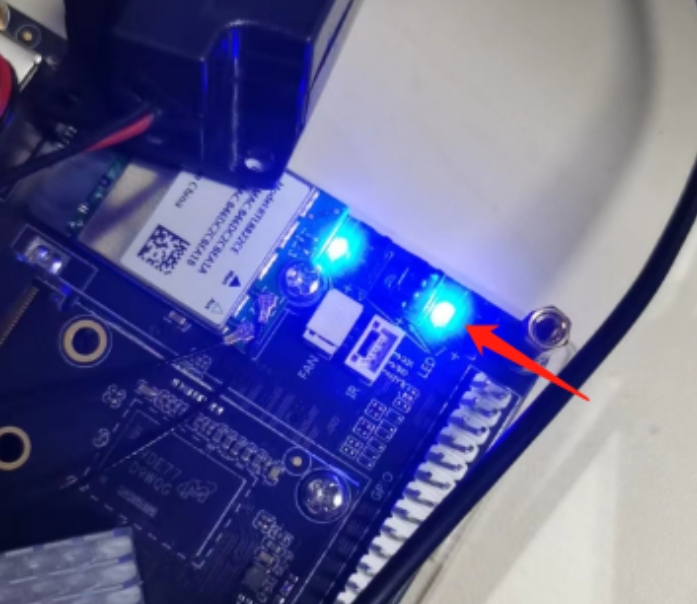
- Turn on Blue1 and follow these steps:
echo 255 > /sys/class/leds/blue1/brightness
- Close Blue1 as follows:
echo 0 > /sys/class/leds/blue1/brightness
