¶ Uart Programming
This chapter introduces the working mode, flow control, use as a console, ttl to usb, ttl to rs232, ttl to rs485 of the YY3588 development board serial port (taking serial port 1 as an example)
Experimental environment: a windows PC computer; a YY3588 development board debian12 system.
¶ 1 Working mode
The serial port has two working modes, namely interrupt mode and DMA mode.
¶ 1.1 Interrupt mode
The kernel configures the serial port to interrupt mode by default. The transmission rate is fast in interrupt mode, but it is easy to lose packets or errors when transmitting large amounts of data. Therefore, please do not use interrupt mode when the amount of data is large. You can consider the following DMA mode.
There is a similar print log
failed to request DMA, use interrupt mode
¶ 1.2 DMA mode
DMA mode is mainly used when transmitting large amounts of data. The kernel will provide a buffer space for the serial port to receive data to minimize the packet loss rate of serial port transmission. The default size of the buffer space is 8K. If a transmission exceeds the buffer size, the packet will be lost. Therefore, if DMA mode is used, the sender needs to send in packets. UART uses DMA transmission mode to significantly reduce the CPU load only when the amount of data is large. Generally speaking, compared with the interrupt transmission mode, UART does not necessarily increase the data transmission speed when using DMA transmission mode.
DTS configuration (taking serial port 1 as an example)
&uart1 {
+++ status = "okay";
+++ dma-names = "tx", "rx";
};
¶ 2 Flow Control
When using hardware automatic flow control for UART, you need to ensure that the UART driver enables the hardware automatic flow control function and that the iomux of the cts and rts flow control pins have been switched in dts. It is recommended to use hardware automatic flow control in scenarios with high baud rates (1.5M baud rate and above) and large amounts of data, that is, to use four-wire UART.
¶ 2.1 Hardware Support
Hardware flow control requires hardware support. Please confirm whether your device supports it.
¶ 2.2 DTS Configuration
&uart1 {
+++ pinctrl-0 = <&uart1m0_xfer &uart1m1_ctsn &uart1m1_rtsn>;
};
¶ 2.3 Application Layer Settings
The application layer also needs to enable flow control settings. Here is how to enable flow control in stty.
¶ 2.3.1 Turn on flow control
# stty -F /dev/ttyS1 crtscts
¶ 2.3.2 Check if flow control is on (a - in front means the function is off)
# stty -F /dev/ttyS1 -a | grep crtscts
-parenb -parodd -cmspar cs8 hupcl -cstopb cread clocal crtscts
¶ 3 As a console
The default uart2 of the YY3588 development board is configured as the ttyFIQ0 device, which is what we call the debug port. Generally, no modification is required.
If the customer needs to configure the ordinary serial port as a console serial port, the corresponding ordinary serial port uart node needs to be disabled, and then the fiq_debugger node needs to be enabled.
¶ 3.1 menuconfig configuration
Device Drivers --->
[*] Staging drivers --->
Android --->
¶ 3.2 DTS configuration
chosen: chosen {
        bootargs = "earlycon=uart8250,mmio32,0xfeb40000 console=ttyFIQ0";
};
fiq-debugger {
    compatible = "rockchip,fiq-debugger";
    rockchip,serial-id = <1>;
    rockchip,wake-irq = <0>;
    /* If enable uart uses irq instead of fiq */
    rockchip,irq-mode-enable = <1>;
    rockchip,baudrate = <1500000>; /* Only 115200 and 1500000 */
    interrupts = <GIC_SPI 252 IRQ_TYPE_LEVEL_LOW>;
    pinctrl-names = "default";
    pinctrl-0 = <&uart1m0_xfer>;
    status = "okay";
};
&uart2 {
    status = "disabled";
};
Description:
- pinctrl-0 = <&uart1m0_xfer>; # Set to uart1
- bootargs = "earlycon=uart8250,mmio32,0xfeb40000 console=ttyFIQ0"; # Change the base address to uart1
- rockchip,serial-id = <1>; # Change to the serial port number you want
- rockchip,irq-mode-enable = <0>; # Configure to 1 to use irq interrupt, configure to 0 to use fiq interrupt.
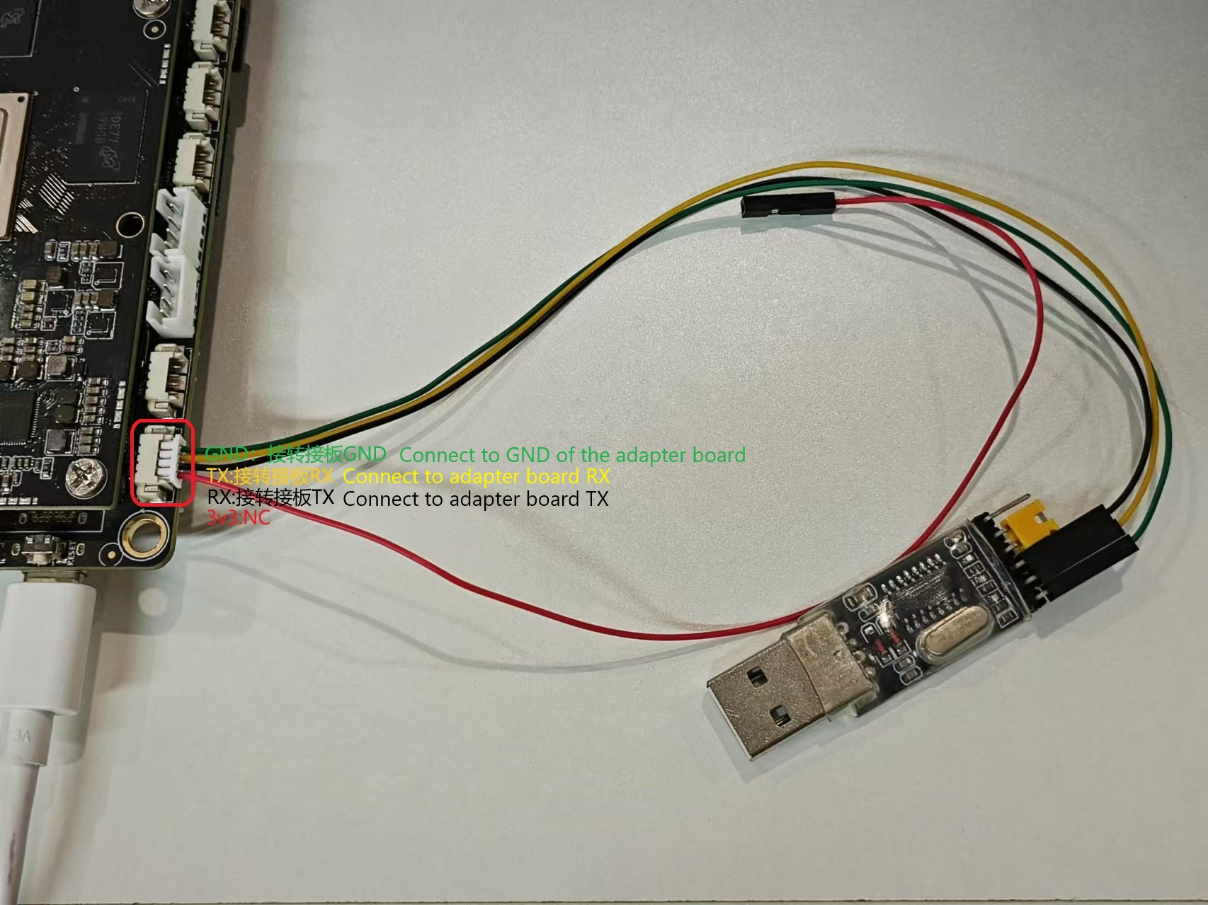
¶ 4 TTL to USB board
¶ 4.0 Preparation
- Make sure the CH340 driver is installed on the PC.
- One TTL to USB module
- One 4pin1.25 terminal cable
¶ 4.1 Hardware connection
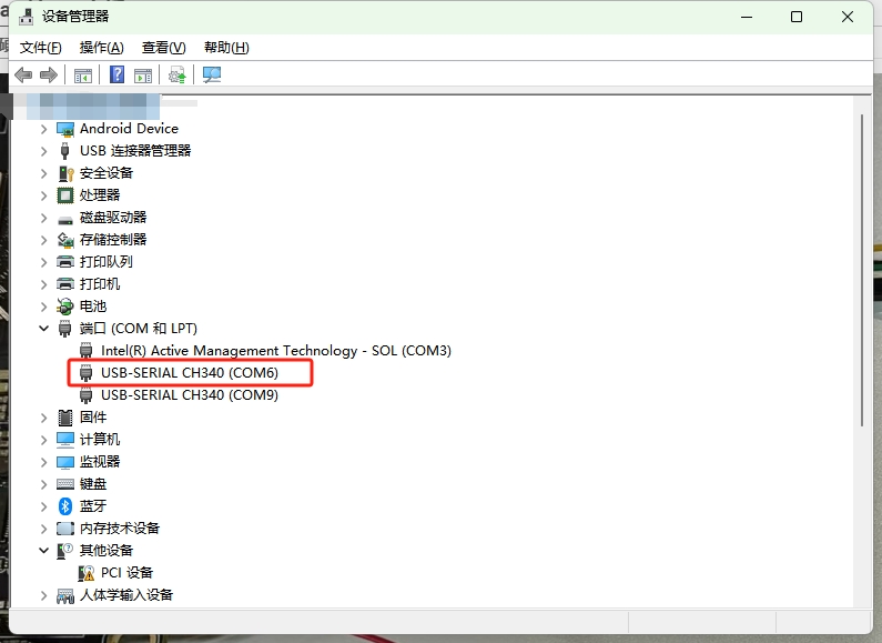
¶ 4.2 Software view
¶ 4.2.1 Find the serial port number of the device manager
¶ 4.2.2 Configure the baud rate on the computer software and the board
- Baud rate: 1500000
- Data bits: 8
- Stop bits: 1
- Parity check: None
- Flow control: None
¶ 4.2.3 Test sending and receiving
Here we demonstrate the free version of the
mobaxtermsoftware, and the animated picture is as follows
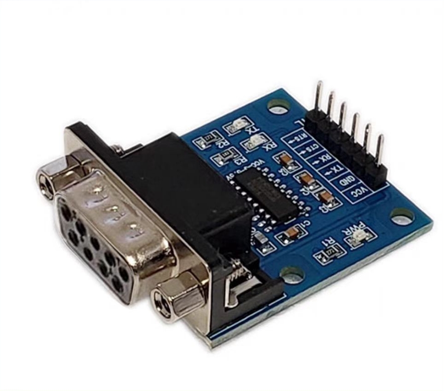
¶ 5 TTL to RS232
¶ 5.0 Preparation
- Make sure the PL2303 driver is installed on the PC
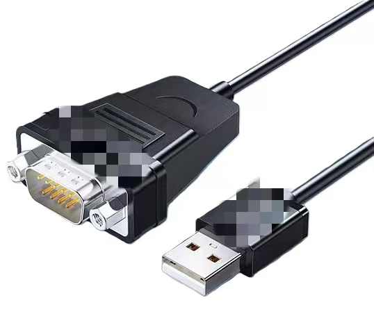
- A TTL to RS232 module
- A RS232 to USB module
- A 4pin1.25 terminal connection cable
¶ 5.1 Hardware connection
- Overall connection
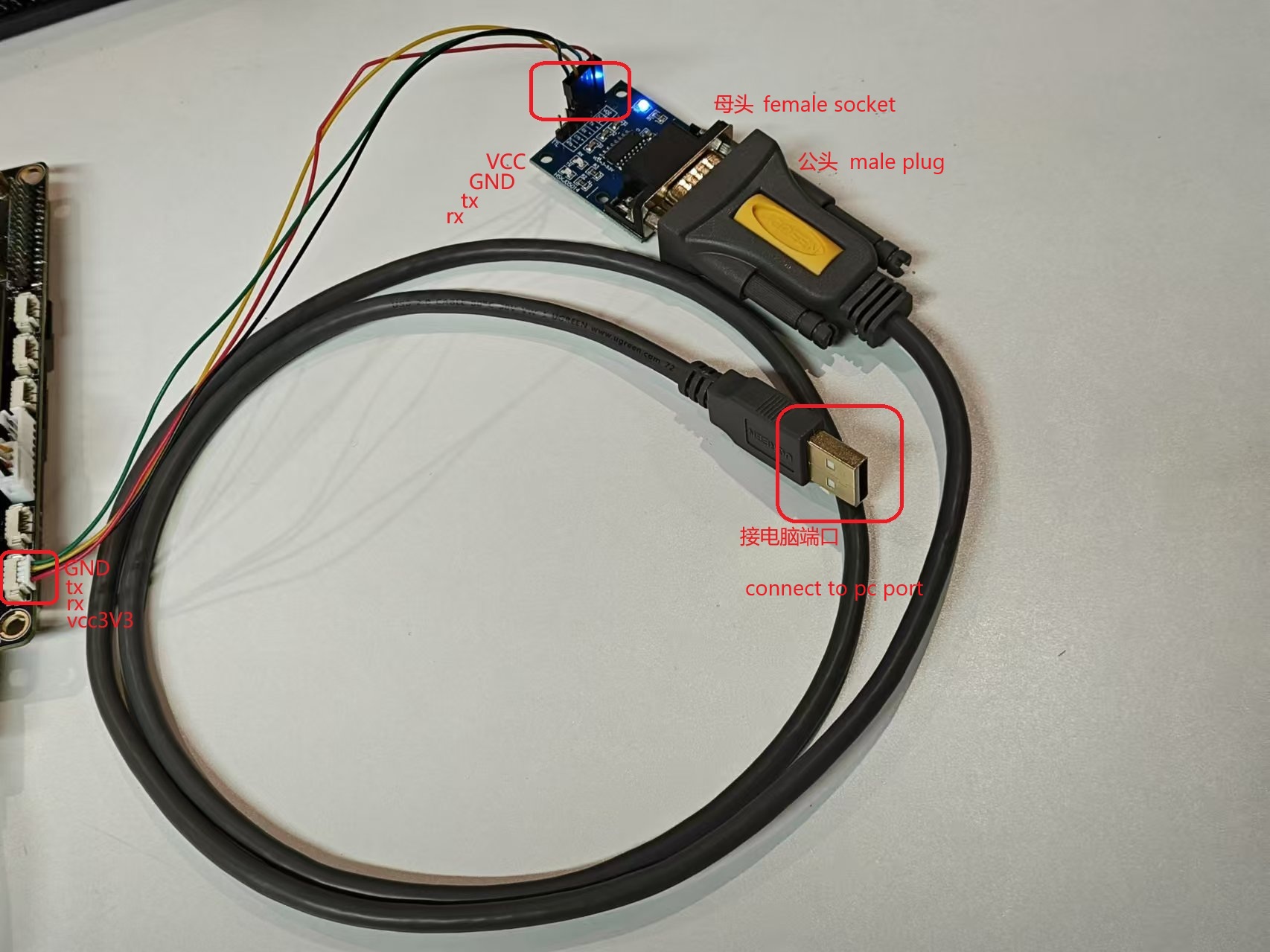
| Port | Board end | TTL to RS232 module end |
|---|---|---|
| Corresponding | TX | TX |
| Corresponding | RX | RX |
| Corresponding | VCC | VCC |
| Corresponding | GND | GND |
- Module diagram
¶ 5.2 Software sending and receiving
¶ 5.2.1 Find the serial port number of the device manager

¶ 5.2.2 Configure the baud rate on the computer software and the board
- Baud rate: 1500000
- Data bits: 8
- Stop bits: 1
- Parity check: None
- Flow control: None
¶ 5.2.3 Test sending and receiving
Here is a demonstration with the free version of
mobaxtermsoftware, the animated picture is as follows
¶ 6 Using 485
// TO DO