¶ I2C Driver for SSD13xx
¶ 1. Introduction
The SSD13xx series is a family of highly integrated single-chip ICs that internally integrate OLED Common/Segment drivers, display RAM, controller, DC/DC boost converter, and oscillator. This high integration design allows OLED modules to be implemented with just a simple connection between the OLED panel and driver IC, without requiring additional backlight or LED driver circuits. The module thickness can be controlled to around 1~1.5mm, making it ideal for space-constrained portable devices. SSD1306 is the most widely known monochrome driver chip. SSD1315 adds scrolling functionality on top of SSD1306, while maintaining consistency with SSD1306 in other aspects.
Most of the I2C resources on YY3588 have their respective dedicated purposes. This document uses GPIO to simulate I2C to drive the SSD13159 OLED screen (OLED screens using SSD131x driver can actually use SSD130x driver, for example, this document actually uses SSD1307 to drive SSD13159, which is theoretically also compatible with SSD1306).
All content used in this document includes:
If you only want to drive the SSD13xx OLED screen without caring about which pins to use, you can directly flash our built boot.img image.
¶ 2. Direct Flashing of boot.img
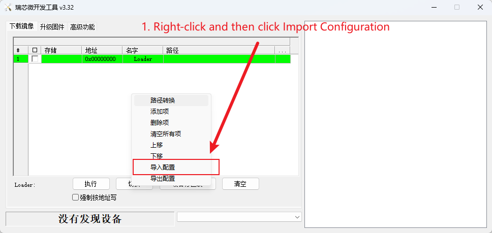
Open RKDevTool, right-click and select Import Configuration.
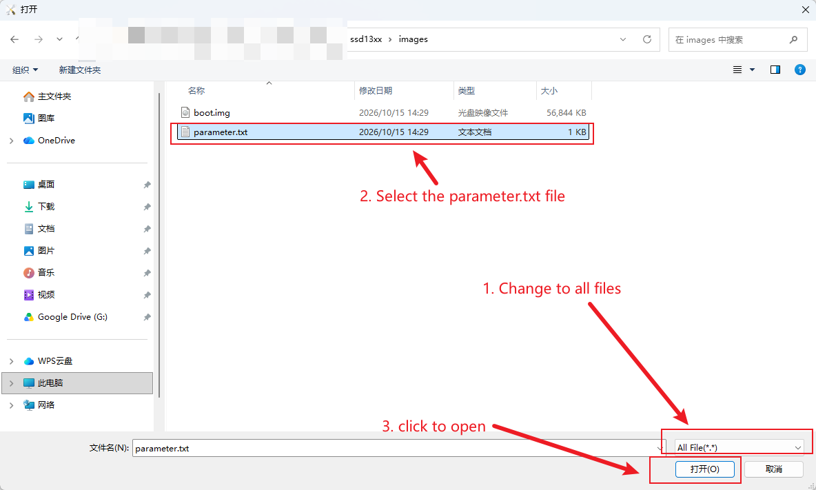
In the pop-up window, select the parameter.txt file in our ssd13xx/images directory.
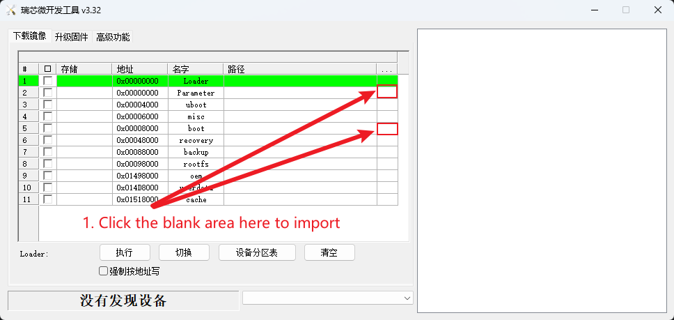
After clicking Open, RKDevTool will load our partition table. Then click the empty space next to it to select our boot.img and parameter.txt files.
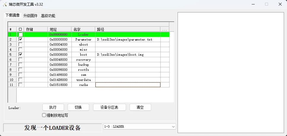
Finally, ensure the device is in loader mode or maskrom mode, then click Execute. After flashing is complete, SSD13xx will be supported.
¶ 3. Building Kernel with SSD13xx Support
If you flashed boot.img in the previous step, skip this section. Before executing the build, you need to modify or replace (choose either replace or modify) the following files in the YY3588 Ubuntu source code directory:
- kernel-6.1/arch/arm64/boot/dts/rockchip/rk3588-evb7-v11-yyt.dtsi
- kernel-6.1/arch/arm64/configs/rockchip_linux_docker.config
¶ 3.1. Replacement
Directly use the files in the ssd13xx/replace directory to replace files in the YY3588 Ubuntu source code.
¶ 3.2. Modification
Add the following configuration items to the file kernel-6.1/arch/arm64/configs/rockchip_linux_docker.config:
CONFIG_I2C_GPIO=y
CONFIG_FB=y
CONFIG_FB_SYS_FILLRECT=y
CONFIG_FB_SYS_COPYAREA=y
CONFIG_FB_SYS_IMAGEBLIT=y
CONFIG_FB_SYS_FOPS=y
CONFIG_FB_DEFERRED_IO=y
CONFIG_FB_SSD1307=y
The complete file content should be:
CONFIG_BRIDGE_NETFILTER=y
CONFIG_MEMCG=y
CONFIG_VETH=y
CONFIG_BRIDGE=y
CONFIG_BRIDGE_NETFILTER=y
CONFIG_IP_NF_FILTER=y
CONFIG_IP_NF_TARGET_MASQUERADE=y
CONFIG_NETFILTER_XT_MATCH_ADDRTYPE=y
CONFIG_NETFILTER_XT_MATCH_CONNTRACK=y
CONFIG_NETFILTER_XT_MATCH_IPVS=y
CONFIG_NETFILTER_XT_MARK=y
CONFIG_IP_NF_NAT=y
CONFIG_NF_CONNTRACK=y
CONFIG_NF_NAT=y
CONFIG_POSIX_MQUEUE=y
CONFIG_CGROUP_BPF=y

CONFIG_I2C_GPIO=y
CONFIG_FB=y
CONFIG_FB_SYS_FILLRECT=y
CONFIG_FB_SYS_COPYAREA=y
CONFIG_FB_SYS_IMAGEBLIT=y
CONFIG_FB_SYS_FOPS=y
CONFIG_FB_DEFERRED_IO=y
CONFIG_FB_SSD1307=y
Device Tree Configuration:
The device tree reuses GPIO2_B2 as SDA and GPIO2_B1 as SCL. Add the following node under the root node in kernel-6.1/arch/arm64/boot/dts/rockchip/rk3588-evb7-v11-yyt.dtsi:
i2c_gpio_ssd1306: i2c-gpio-ssd1306 {
      compatible = "i2c-gpio";
      status = "okay";
      pinctrl-names = "default";
      pinctrl-0 = <&i2c_gpio_pins>;

      gpios = <&gpio2 RK_PB2 (GPIO_ACTIVE_HIGH | GPIO_OPEN_DRAIN)>,
          <&gpio2 RK_PB1 (GPIO_ACTIVE_HIGH | GPIO_OPEN_DRAIN)>;

      i2c-gpio,delay-us = <5>;
      i2c-gpio,timeout-ms = <1000>;
      #address-cells = <1>;
      #size-cells = <0>;

      ssd1315: ssd1315@3c {
        compatible = "solomon,ssd1306fb-i2c";
        reg = <0x3c>;
        solomon,height = <64>;
        solomon,width = <128>;
        solomon,page-offset = <0>;
        solomon,com-offset = <0>;
        solomon,prechargep1 = <1>;
        solomon,prechargep2 = <15>;
        reset-gpios = <&gpio2 RK_PC0 GPIO_ACTIVE_LOW>;
      };
    };

Also, add the following node in the pinctrl node of the file rk3588-evb7-v11-yyt.dtsi:
i2c-gpio {
    i2c_gpio_pins: i2c-gpio-pins {
      rockchip,pins =
        /* SDA: GPIO2_B2 */
        <2 RK_PB2 RK_FUNC_GPIO &pcfg_pull_up>,
        /* SCL: GPIO2_B1 */
        <2 RK_PB1 RK_FUNC_GPIO &pcfg_pull_up>;
    };
  };
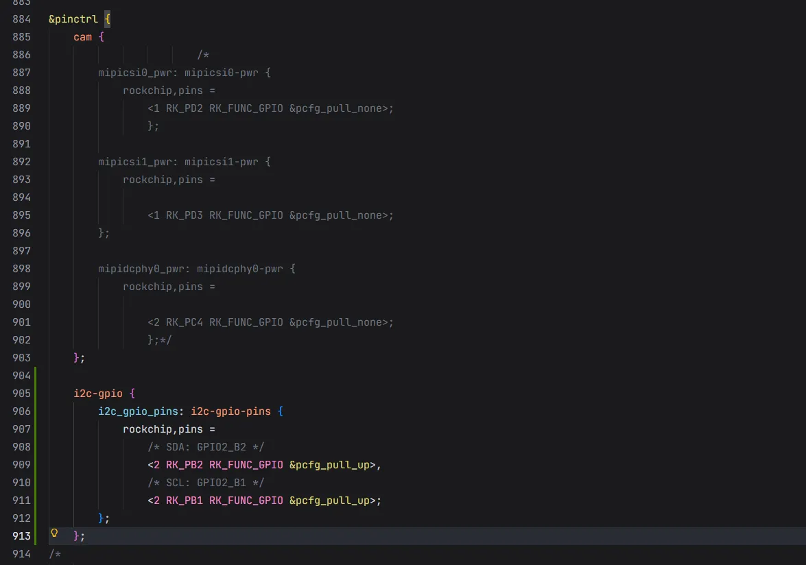
After saving, run the following command to compile:
./yy3588-build.sh
Build the complete firmware, then flash the built complete firmware update.img to the board.
¶ 4. Hardware Connection
Connect the hardware as follows. Refer to the YY3588 hardware schematic for detailed pin locations:
| YY3588 | SSD13xx 0.96 OLED |
|---|---|
| 3.3V | VCC |
| GND | GND |
| GPIO2_B1 (pin 12) | SCL |
| GPIO2_B2 (pin 10) | SDA |
Actual wiring:
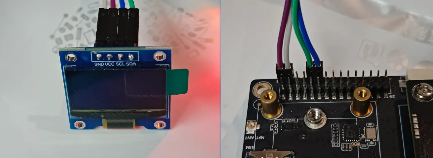
After flashing and connecting, the screen will have a blinking underscore similar to a terminal cursor. At this point, the screen has entered normal working state. You can verify this through kernel logs or using i2ctools (located in the ssd13xx/tools/i2c-tools/ directory). All subsequent commands are executed in ADB.
¶ 5. Checking Connection Status
You can determine whether ssd13xx is properly recognized by the system using the following methods:
¶ 5.1 Check Kernel Logs
Execute the following command to view kernel logs:
dmesg | grep i2c
Output:
root@YY3588:/home/youyeetoo# dmesg | grep i2c
[    1.920597] i2c-gpio i2c-gpio-ssd1306: using lines 74 (SDA) and 73 (SCL)
[    2.894939] i2c_dev: i2c /dev entries driver
[    2.915928] i2c 2-0037: Fixed dependency cycle(s) with /csi2-dcphy0/ports/port@0/endpoint@1
[    3.835882] <<-GTP-ERROR->> GTP i2c test failed time 1.
[    3.963880] <<-GTP-ERROR->> GTP i2c test failed time 2.
[    4.091881] <<-GTP-ERROR->> GTP i2c test failed time 3.
[    4.219882] <<-GTP-ERROR->> GTP i2c test failed time 4.
[    4.347882] <<-GTP-ERROR->> GTP i2c test failed time 5.
[    4.368096]  i2c_device_probe+0x138/0x350
[    4.368172]  i2c_new_client_device+0x184/0x340
[    4.368179]  of_i2c_register_devices+0x15c/0x210
[    4.368187]  i2c_register_adapter+0x1e4/0x6b4
[    4.368194]  __i2c_add_numbered_adapter+0x60/0xac
[    4.368201]  i2c_add_numbered_adapter+0x20/0x34
[    4.368208]  rk3x_i2c_probe+0x354/0x514
[    4.368280]  rk3x_i2c_driver_init+0x20/0x28
[    4.376727] i2c 4-0037: Fixed dependency cycle(s) with /csi2-dcphy1/ports/port@0/endpoint@1
[    5.295883] <<-GTP-ERROR->> GTP i2c test failed time 1.
[    5.423882] <<-GTP-ERROR->> GTP i2c test failed time 2.
[    5.551879] <<-GTP-ERROR->> GTP i2c test failed time 3.
[    5.679882] <<-GTP-ERROR->> GTP i2c test failed time 4.
[    5.807882] <<-GTP-ERROR->> GTP i2c test failed time 5.
[    5.828085]  i2c_device_probe+0x138/0x350
[    5.828159]  i2c_new_client_device+0x184/0x340
[    5.828166]  of_i2c_register_devices+0x15c/0x210
[    5.828173]  i2c_register_adapter+0x1e4/0x6b4
[    5.828180]  __i2c_add_numbered_adapter+0x60/0xac
[    5.828187]  i2c_add_numbered_adapter+0x20/0x34
[    5.828193]  rk3x_i2c_probe+0x354/0x514
[    5.828264]  rk3x_i2c_driver_init+0x20/0x28
[    5.836740] i2c 6-0022: Fixed dependency cycle(s) with /usbdrd3_0/usb@fc000000/port/endpoint@0
From:
[ 1.920597] i2c-gpio i2c-gpio-ssd1306: using lines 74 (SDA) and 73 (SCL)
You can see that the driver has been loaded, using GPIO with pin number 74 as SDA and pin number 73 as SCL.
Execute:
dmesg | grep ssd
Output:
root@YY3588:/home/youyeetoo# dmesg | grep ssd
[    1.920597] i2c-gpio i2c-gpio-ssd1306: using lines 74 (SDA) and 73 (SCL)
[    2.679150] ssd1307fb 9-003c: fb0: Solomon SSD1307 framebuffer device registered, using 1024 bytes of video memory
You can see that the device has been successfully recognized. If the output is:
root@YY3588:/# dmesg | grep ssd
[    1.918853] i2c-gpio i2c-gpio-ssd1306: using lines 74 (SDA) and 73 (SCL)
[    2.257087] ssd1307fb 9-003c: Couldn't send I2C command.
This indicates that the hardware is not correctly connected, especially check if SCL and SDA are reversed.
¶ 5.2 Using i2ctools
First, execute the following command to list all I2C devices on the board:
./i2cdetect -l
Output:
root@YY3588:/home/youyeetoo/tools# ./i2cdetect -l
i2c-0   i2c             rk3x-i2c                                I2C adapter
i2c-1   i2c             rk3x-i2c                                I2C adapter
i2c-2   i2c             rk3x-i2c                                I2C adapter
i2c-3   i2c             rk3x-i2c                                I2C adapter
i2c-4   i2c             rk3x-i2c                                I2C adapter
i2c-5   i2c             rk3x-i2c                                I2C adapter
i2c-6   i2c             rk3x-i2c                                I2C adapter
i2c-7   i2c             rk3x-i2c                                I2C adapter
i2c-9   i2c             i2c-gpio-ssd1306                        I2C adapter
i2c-10  i2c             DP-AUX                                  I2C adapter
i2c-11  i2c             ddc                                     I2C adapter
i2c-12  i2c             fde50000.dp                             I2C adapter
Where i2c-9 is our GPIO-simulated I2C. Next, execute the following command to check the status of i2c-9 (where 9 indicates viewing information for i2c-9):
root@YY3588:/home/youyeetoo/tools# ./i2cdetect -y 9
     0  1  2  3  4  5  6  7  8  9  a  b  c  d  e  f
00:                         -- -- -- -- -- -- -- --
10: -- -- -- -- -- -- -- -- -- -- -- -- -- -- -- --
20: -- -- -- -- -- -- -- -- -- -- -- -- -- -- -- --
30: -- -- -- -- -- -- -- -- -- -- -- -- UU -- -- --
40: -- -- -- -- -- -- -- -- -- -- -- -- -- -- -- --
50: -- -- -- -- -- -- -- -- -- -- -- -- -- -- -- --
60: -- -- -- -- -- -- -- -- -- -- -- -- -- -- -- --
70: -- -- -- -- -- -- -- --
First look at row 30, then column c. At their intersection, there is a "UU" mark. The UU mark indicates a detected communication address that is already occupied by the kernel. So the output means that at address 0x30+0x0c, i.e., 0x3c, there exists a communication address occupied by the kernel. This address is the I2C communication address of SSD13159. If the hardware connection is incorrect, it will not be recognized, and the output will be:
root@YY3588:/home/youyeetoo/tools# ./i2cdetect -y 9
     0  1  2  3  4  5  6  7  8  9  a  b  c  d  e  f
00:                         -- -- -- -- -- -- -- --
10: -- -- -- -- -- -- -- -- -- -- -- -- -- -- -- --
20: -- -- -- -- -- -- -- -- -- -- -- -- -- -- -- --
30: -- -- -- -- -- -- -- -- -- -- -- -- -- -- -- --
40: -- -- -- -- -- -- -- -- -- -- -- -- -- -- -- --
50: -- -- -- -- -- -- -- -- -- -- -- -- -- -- -- --
60: -- -- -- -- -- -- -- -- -- -- -- -- -- -- -- --
70: -- -- -- -- -- -- -- --
If the hardware is properly connected, the SSD1315 device will eventually be recognized as an fb (framebuffer) device. You can use the following command to view what fb devices are on the system:
ls -l /dev/fb*
Output:
root@YY3588:/home/youyeetoo/tools# ls -l /dev/fb*
crw------- 1 root root 29, 0 Jun  4 22:36 /dev/fb0
crw------- 1 root root 29, 1 Jun  4 22:17 /dev/fb1
Next, determine which fb device corresponds to the SSD1315. Execute:
cat /sys/class/graphics/fb0/name
cat /sys/class/graphics/fb1/name
Output:
root@YY3588:/home/youyeetoo/tools# cat /sys/class/graphics/fb0/name
Solomon SSD1307
root@YY3588:/home/youyeetoo/tools# cat /sys/class/graphics/fb1/name
rockchipdrmfb
You can see that fb0 is the fb device we're looking for (using the SSD1307 driver, but actually SSD13159). You can then use the following commands to write data to /dev/fb0 for simple testing:
# Clear screen - all black
dd if=/dev/zero of=/dev/fb0 bs=1024 count=1

# All white
dd if=/dev/zero bs=1 count=1024 | tr '\000' '\377' > /dev/fb0
¶ 5.3 Disabling SSD13xx Blinking
Now, back to the blinking underscore cursor mentioned earlier on the screen. This blinking cursor is the Linux console cursor. When SSD1315 is recognized as /dev/fb0, the kernel automatically uses it as a console output device, just like a terminal screen. The cursor is the command-line prompt cursor. The Linux kernel detects the framebuffer device during startup and binds the console to this framebuffer. If you don't want to display this cursor, follow these steps. First, check what virtual consoles exist:
ls /sys/class/vtconsole/
Output:
root@YY3588:/home/youyeetoo/tools# ls /sys/class/vtconsole/
vtcon0  vtcon1
We learn that there are two virtual consoles: vtcon0 and vtcon1. Next, check the name attribute of these two virtual consoles:
cat /sys/class/vtconsole/vtcon*/name
root@YY3588:/home/youyeetoo/tools# cat /sys/class/vtconsole/vtcon*/name
(S) dummy device
(M) frame buffer device
Where "(S) dummy device" is the result for vtcon0, and "(M) frame buffer device" is the result for vtcon1. You can also execute them separately to confirm. (M) indicates Main console, and (S) indicates Secondary console.
cat /sys/class/vtconsole/vtcon0/name
cat /sys/class/vtconsole/vtcon1/name
Output:
root@YY3588:/home/youyeetoo/tools# cat /sys/class/vtconsole/vtcon0/name
(S) dummy device
root@YY3588:/home/youyeetoo/tools# cat /sys/class/vtconsole/vtcon1/name
(M) frame buffer device
We can conclude that vtcon1 is the virtual console we're looking for. Next, check the binding status:
cat /sys/class/vtconsole/vtcon*/bind
The output is similar to the name attribute mentioned earlier:
root@YY3588:/home/youyeetoo/tools# cat /sys/class/vtconsole/vtcon*/bind
0
1
The first output corresponds to vtcon0's binding status, with a value of 0 indicating currently unbound. The second output corresponds to vtcon1's result, with a value of 1 indicating currently bound. You can write 0 to this file to unbind it, and the blinking will stop:
echo 0 > /sys/class/vtconsole/vtcon1/bind
You can also restore binding by writing 1:
echo 1 > /sys/class/vtconsole/vtcon1/bind
These two commands will not produce output. You need to observe the screen state to determine the execution result, or execute:
echo $?
A return value of 0 indicates successful execution.
Linux VT Console Principle:
┌─────────────────────────────────────┐
│   Application output to /dev/console │
└──────────────┬──────────────────────┘
               │
               ▼
┌─────────────────────────────────────┐
│      Kernel VT Subsystem            │
│  ┌─────────┐      ┌──────────┐     │
│  │ vtcon0  │      │  vtcon1  │     │
│  │ (dummy) │      │   (fb)   │     │
│  │ bind=0  │      │  bind=1  │◄────── Currently active
│  └─────────┘      └────┬─────┘     │
└────────────────────────┼───────────┘
                         │
                         ▼
                   ┌──────────┐
                   │ /dev/fb0 │
                   │(SSD1315) │
                   └──────────┘
¶ 6. Driver Source Code
ssd13xx/
├── driver/                       # Core library source code
│   ├── ssd13xx_driver.c/h        # Display driver core
│   ├── font_ascii.c              # ASCII font data
│   ├── font_chinese.c            # Chinese font data
│   ├── text_render.c             # Text rendering engine
│   ├── font.h                    # Font API interface
│   └── utf8_gb2312_table.h       # UTF-8 to GB2312 mapping table
│
├── example/                      # Example programs
│   ├── ascii.c                   # ASCII character display example
│   ├── chinese.c                 # Chinese character display example
│   ├── mixed.c                   # Mixed Chinese/English display example
│   └── shape.c                   # Graphics drawing example
│
├── tools/                        # Development tools
│   ├── debug_chinese_font.c      # Font bitmap visualization tool
│   ├── font_ascii_converter.c    # ASCII font conversion tool
│   ├── font_chinese_converter.c  # Chinese font conversion tool
│   └── i2c-tools/                # i2c-tools
│
├── docs/                         # Documentation
│   ├── README.md                 # Documentation index
│   ├── zh-cn/                    # Chinese documentation
│   │   ├── API.md                # API reference
│   │   ├── BUILD.md              # Build guide
│   │   ├── EXAMPLE.md            # Example programs guide
│   │   └── TOOLS.md              # Development tools guide
│   └── en/                       # English documentation
│       ├── API.md
│       ├── BUILD.md
│       ├── EXAMPLE.md
│       └── TOOLS.md
│
├── build/                        # Build intermediate files (.o)
├── output/                       # Output directory
│   ├── examples/                 # Example program executables
│   └── tools/                    # Development tool executables
├── Makefile                      # Build system
└── README.md                     # This file
The source code already implements 5x7, 6x12, 8x8, and 8x16 ASCII font libraries, as well as a small number of Chinese characters for testing purposes. For details, please refer to the example program code in the example directory. For quick verification, you can execute the compiled executables in the bin directory.
¶ 7. Font Library Creation
The following section details how to add Chinese font libraries.
¶ 7.1 Font Library Creation
The following section details how to add Chinese font libraries.
¶ 7.2 Font Bitmap Generation
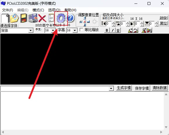
The bitmap generation tool used here is PCtoLCD2002. Download address:
First, click to open Settings.
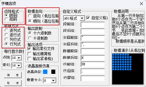
Set the dot matrix format to Negative, conversion mode to Row-Column, and conversion direction to Forward (high bit first). Click OK in the lower left corner to return to the main page.
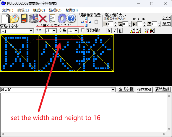
Next, set the width and height of the character. For Chinese characters to display clearly and be easily recognizable, the character size should not be less than 12x12. This driver implements 12x12 and 16x16 drivers, which can be used as needed. Here we use 16x16 as an example.
The generated result is shown below, but the raw data of the generated font bitmap cannot be directly applied to the code and needs to be converted through data format conversion.
¶ 8. Font Bitmap Conversion
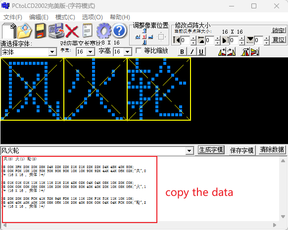
Open the ssd13xx driver source code directory and use font_chinese_converter in the output/tools directory for conversion. For specific usage, refer to the TOOLS.md document in the docs directory.
¶ 9. Adding Font Bitmaps
Add the converted data to the corresponding array in driver/font_chinese.c. Here it's 16x16 size, so add it to the chinese_font_16x16 array. If it's 12x12, add it to the chinese_font_12x12 array.
static const chinese_char_t chinese_font_16x16[] = {

  /* 你 (ni3) - GB2312: C4E3 */
  {0xC4E3, {
    0x08,0x80, 0x08,0x80, 0x08,0x80, 0x11,0xFE,
    0x11,0x02, 0x32,0x04, 0x34,0x20, 0x50,0x20,
    0x91,0x28, 0x11,0x24, 0x12,0x24, 0x12,0x22,
    0x14,0x22, 0x10,0x20, 0x10,0xA0, 0x10,0x40}},

  /* 好 (hao3) - GB2312: BAC3 */
  {0xBAC3, {
    0x10,0x00, 0x10,0xFC, 0x10,0x04, 0x10,0x08,
    0xFC,0x10, 0x24,0x20, 0x24,0x20, 0x25,0xFE,
    0x24,0x20, 0x48,0x20, 0x28,0x20, 0x10,0x20,
    0x28,0x20, 0x44,0x20, 0x84,0xA0, 0x00,0x40}},

  /* ....... */

  /* 风 - GB2312: B7E7 */
  {0xB7E7, {
    0x00,0x00, 0x3F,0xF0, 0x20,0x10, 0x20,0x10,
    0x28,0x50, 0x24,0x50, 0x22,0x90, 0x22,0x90,
    0x21,0x10, 0x21,0x10, 0x22,0x90, 0x22,0x92,
    0x24,0x4A, 0x48,0x4A, 0x40,0x06, 0x80,0x02}},

  /* 火 - GB2312: BBF0 */
  {0xBBF0, {
    0x01,0x00, 0x01,0x00, 0x01,0x00, 0x11,0x08,
    0x11,0x08, 0x11,0x10, 0x21,0x20, 0x21,0x00,
    0x42,0x80, 0x02,0x80, 0x04,0x40, 0x04,0x40,
    0x08,0x20, 0x10,0x10, 0x20,0x08, 0xC0,0x06}},

  /* 轮 - GB2312: C2D6 */
  {0xC2D6, {
    0x20,0x40, 0x20,0x40, 0x20,0xA0, 0xFC,0xA0,
    0x41,0x10, 0x52,0x08, 0x94,0x06, 0xFD,0x10,
    0x11,0x20, 0x11,0x40, 0x1D,0x80, 0xF1,0x00,
    0x51,0x04, 0x11,0x04, 0x10,0xFC, 0x10,0x00}}
};
Also add the UTF-8 to GB2312 mapping in the mapping table in driver/utf8_gb2312_table.h:
static const utf8_gb_map_t utf8_to_gb2312_table[] = {

    /* Characters already in the project */
    {0x4E16, 0xCAC0, "世"},
    {0x4F60, 0xC4E3, "你"},
    {0x597D, 0xBAC3, "好"},
    {0x5EA6, 0xB6C8, "度"},
    {0x663E, 0xCFD4, "显"},
    {0x6D4B, 0xB2E2, "测"},
    {0x6E29, 0xCEC2, "温"},
    {0x754C, 0xBDE7, "界"},
    {0x793A, 0xCABE, "示"},
    {0x8BD5, 0xCAD4, "试"},
    {0x98CE, 0xB7E7, "风"},
    {0x706B, 0xBBF0, "火"},
    {0x8F6E, 0xC2D6, "轮"},

    /* More characters can be added... */
    /* Format: {Unicode codepoint, GB2312 encoding, "character"}, */
};
At this point, the font library is ready for use. For specific display examples, refer to the example programs in the example directory. You can also use get.py in the tools directory to quickly obtain Unicode encoding and GB2312 encoding. For detailed usage, refer to the TOOLS.md document in the docs directory.