¶ GPIO
The full name of GPIO is: General-Purpose Input/Output (General-Purpose Input/Output), which is a general-purpose pin that can be dynamically configured and controlled during software running. On the RK platform, except for some pins with special purposes (such as DDR, MIPI, etc.), other pins, if not configured for multiplexing, are GPIO by default. RK's GPIO driver provides the standard GPIO interface under Linux. There is a set of sysfs nodes for user-mode operation of GPIO under Linux. The application layer programs GPIO mainly by operating these nodes.
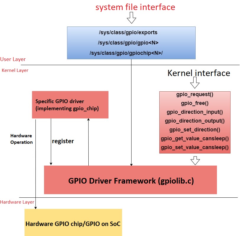
The following is an example of operating GPIO3_A5. The location of this GPIO is as follows


Under the general Linux framework, all GPIOs are numbered. For RK platform chips, the number calculation method is:
(gpio controller number-0)*32+(port number-‘A’)*8+index sequence number
The controller number of GPIO3_A5 is 3, the port number is A, and the index sequence number is 5, so the number is (3-0)×32+0×8+5 =101
¶ Command to operate GPIO
- Set GPIO 101 for user-mode operation
echo 101 > /sys/class/gpio/export
- Set GPIO 101 as output
echo out > /sys/class/gpio/gpio101/direction
- In the case where GPIO 101 is output, set the level
- High Level
echo 1 > /sys/class/gpio/gpio101/value
- Low Level
echo 0 > /sys/class/gpio/gpio101/value
- Set GPIO 101 as input
echo in > /sys/class/gpio/gpio101/direction
- When GPIO 101 is an input, read its level, 1 is high, 0 is low
cat sys/class/gpio/gpio101/value
- Cancel GPIO 101 user state operation
echo 101 > /sys/class/gpio/unexport
- Execution Effect

¶ USB
- Mount the USB disk to the system via USB, as follows:

# mkdir /mnt/usb
# mount /dev/block/sda1 /mnt/usb
# cd /mnt/usb
# ls
- Execution Effect:

¶ UART
Rockchip UART (Universal Asynchronous Receiver/Transmitter) is based on 16550A serial port standard. The kernel uses 8250 serial port universal driver, so it can support standard serial port programming under Linux.
-
There are three general serial ports and one debug serial port on the board. It is recommended not to use the debug serial port for other purposes.

-
The serial numbers of these three universal serial ports are 5, 7, and 9 (if serial port 9 is reused by i2c, it should not be used). The corresponding device nodes under Linux are /dev/ttyS5 /dev/ttyS7 (/dev/ttyS9). The following uses ttyS7 as an example to introduce its usage. The other serial ports are similar.
-
In terms of hardware, use a serial port module to connect TX and RX of ttyS7, baud rate: 9600, the wiring diagram is as follows:

-
Send Data:
echo "youyeetoo" > /dev/ttyS7
Execution Effect:

¶ I2C
- The i2c-tools tool is an open source tool specifically for debugging i2c. It can obtain mounted devices and device addresses, and can also read and write I2C device registers.
- How to use i2c-tools:
- See all i2c buses。
# i2cdetect -l
- View the functions supported by the specified i2c bus
# i2cdetect -F 2
- Check the devices mounted on the i2c-2 bus
# i2cdetect -a -y 2
'UU' appearing in the picture means that there is a device at the address and the device matches the driver
'--' appears in the picture, indicating that there is no device at the address
The appearance of 'number' in the picture indicates that there is a device at the address but the device and driver do not match
- View the value of device register 0x01 at address 0x42 of i2c-2
# i2cget -f -y 2 0x42 0x01
- Execution Effect:

¶ SPI
- Hardware connection
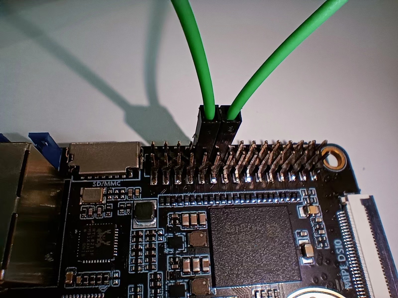
- Note: To test the SPI bus, you need to open the corresponding device node and modify the device tree as follows: rk3588s-evb4-lp4x-yyt.dtsi

- After powering on the development board, perform a loopback test
dmesg -C
echo setspeed 0 1000000 > /dev/spi_misc_test
echo loop 0 10 255 > /dev/spi_misc_test
dmesg
- Execution Effect:

¶ PWM
-
Hardware connection
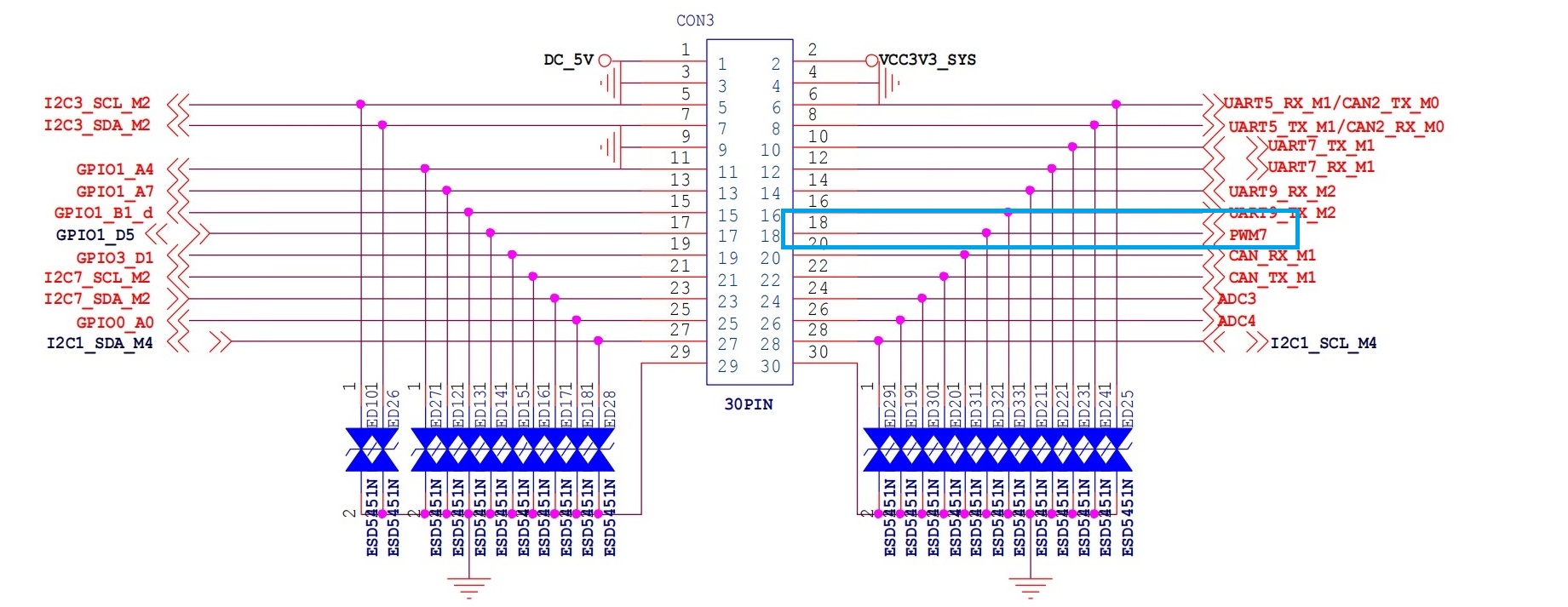
-
To test PWM7 as an example, execute the following command:
# cd /sys/class/pwm/pwmchip0/
# echo 0 > export
# cd pwm0
# echo 10000 > period
# echo 5000 > duty_cycle
# echo 1 > enable
- Execution Results:


¶ CAN
CAN (Controller Area Network) is an efficient and reliable communication protocol for real-time control and data exchange. It was originally developed by BOSCH in Germany and has now become an international standard ISO 11898. The CAN bus adopts a multi-master competitive bus structure, supports multiple nodes to send and receive data at the same time, has error detection and automatic retransmission functions, and can effectively improve the reliability and real-time performance of the system. CAN is widely used in automobiles, industrial automation, robots and other fields, and is an indispensable part of modern electronic systems.
- How to use can
- Query current network equipment
ifconfig -a
- Set can
canconfig  can0 down
canconfig  can0 type can bitrate 1000000 dbitrate 3000000 on
canconfig  can0 up
canconfig  can0 start
//or
canconfig  can0 down
canconfig  can0 type can bitrate 1000000 loopback on
canconfig  can0 up
canconfig  can0 start
- can send and receive
cansend can0 -v -i 12 13 12 12
candump can0
¶ ADC
- ADC (Analog-to-Digital Converter) converts analog signals into digital signals and is commonly used in electronic devices such as audio, video processing and sensor applications.
- The R1 development board is a 12-bit ADC.
- The R1 development board has two ADC channels, and channel 4 is used as an example here. Use the command
cat /sys/bus/iio/devices/iio\:device0/in_voltage4_raw
-
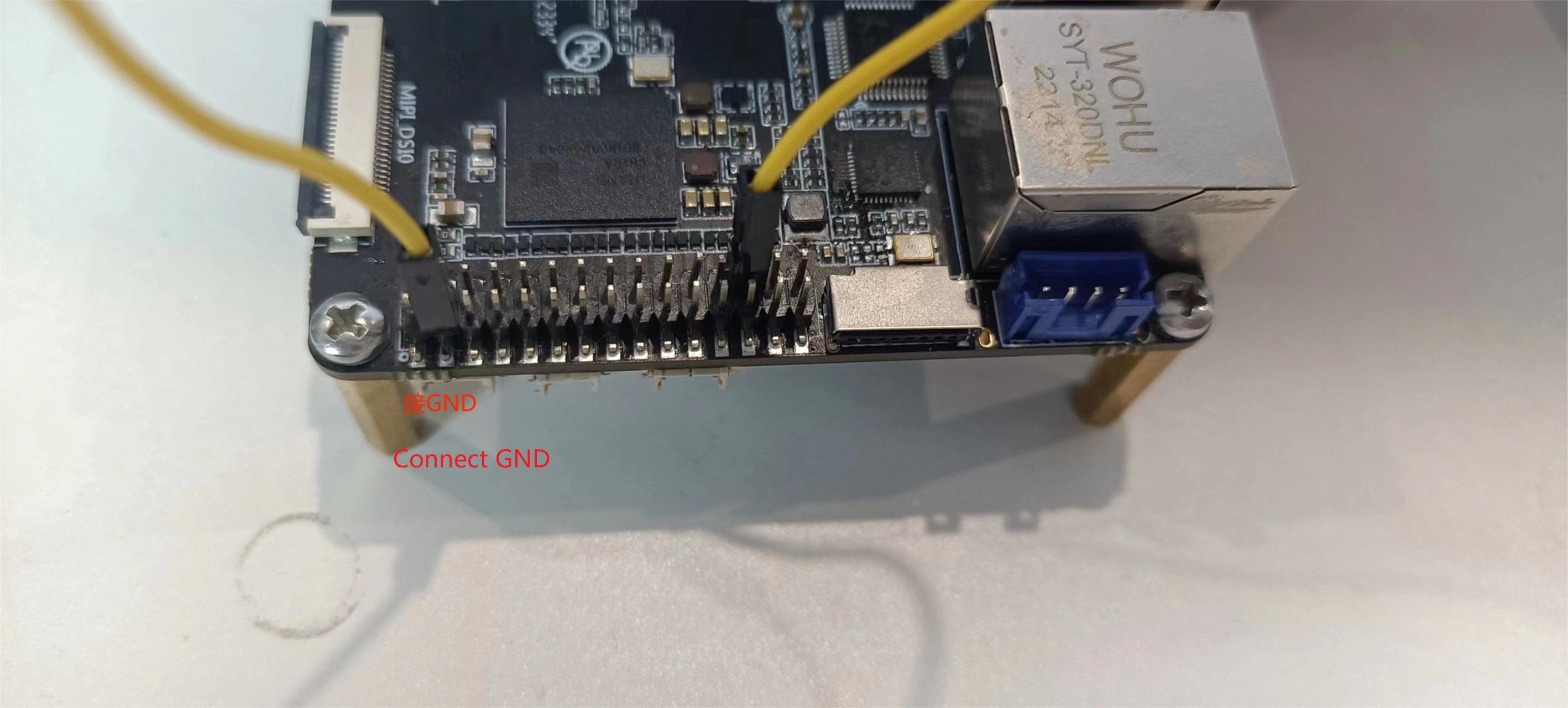
Test to VCC:
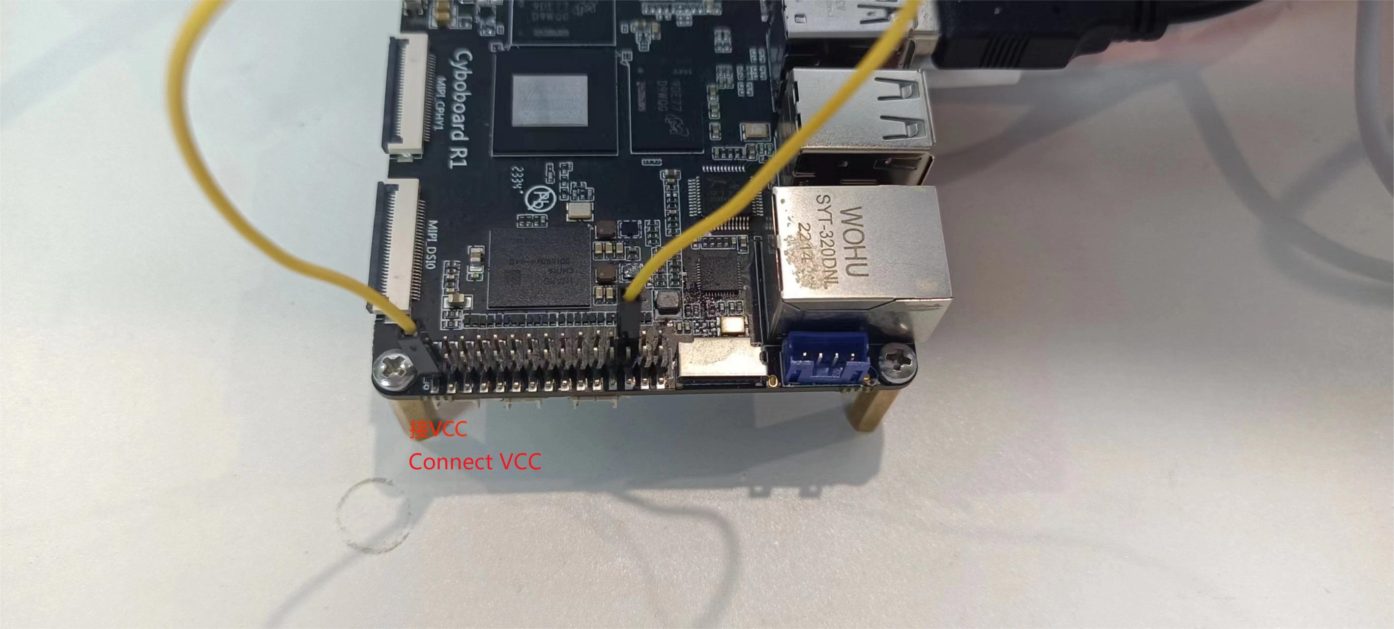
-
Execution Effect:

-
Test to GND:
-
Execution Effect:
