¶ I2C interface read and write test
1.Hardware interface description:
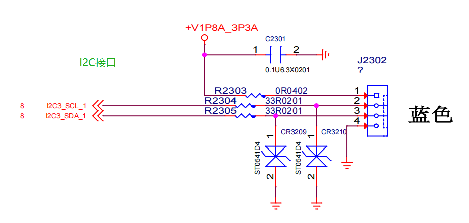
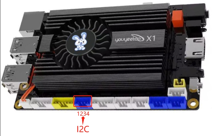
The J2302 socket on the motherboard corresponds to the I2C3 of the CPU, and the socket wiring sequence is explained as follows:
| Serial Number | Description | Remarks |
|---|---|---|
| 1 | VCC | Output voltage 3.3V |
| 2 | I2C3_ SCL | This PIN requires an external 4.7K resistor to be pulled up to VCC |
| 3 | I2C3_ SDA | This PIN requires an external 4.7K resistor to be pulled up to the VCC |
| 4 | GND | Power reference ground |
2、 Adding I2C Slave Devices to BIOS
Adding method: Please refer to the following section of the "Windows Driver Development" description. Here, only the ASL code that needs to be added is indicated. The key information is annotated in Chinese and modified according to the actual hardware. It should be emphasized that Chinese cannot appear in the formal ASL code, and the Chinese annotations should be removed or replaced with English annotations
Add an I2C device to the following ASL code, and modify the key three items according to the actual situation:
| Project | Description Value | Remarks |
|---|---|---|
| Device driver ID | I2C30001 | The associated hardware ID corresponding to the driver program |
| I2C Slave device address | 0X50 | I2C peripheral slave 7-bit address, excluding read/write bits |
| I2C rate | 0x00061A80 | I2C rate, supporting commonly used 100K, 400K, etc. Here is 400K |
    Scope (_SB.PC00.I2C3)
    {
        Device (EPC3)
        {
            Name (_ADR, Zero)
            Name (_HID, "I2C30001")  // _HID:Hardware ID, device manager display, and driver configuration used
            Name (_CID, "I2C30001")  // _CID:Compatible ID, and_ HID is sufficient
            Name (_S0W, Zero)
            Name (_UID, One)
            Method (_CRS, 0, NotSerialized)
            {
                Name (RBUF, ResourceTemplate ()
                {

                    I2cSerialBusV2 (0x50, //I2C slave device address: 7-bit representation, excluding read/write bits
                    ControllerInitiated,
                    0x00061A80,							//Speed, here is 400K
                    AddressingMode7Bit,
                    "\\_SB.PC00.I2C3",
                    0x00, ResourceConsumer, , Exclusive,
                        )
                })
                Return (RBUF)
            }

            Method (_STA, 0, NotSerialized)
            {
                Return (0x0F)
            }
        }

    }
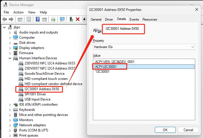
After adding the I2C device to the BIOS, you can view it from the Device Manager: Unknown device, corresponding hardware ID, and description in the ASL code_ Same as HID (I2C30001), as shown in the figure
3、 Device ID and Driver Association
We will provide an I2C driver and add the hardware ID I2C30001 to the driver installation file "SpbDriver. inf". The full text of the driver file is as follows:
[Version]
Signature   = "$WINDOWS NT$"
Class = HIDClass
ClassGuid ={745a17a0-74d3-11d0-b6fe-00a0c90f57da}

Provider    = %ProviderName%
DriverVer = 08/13/2023,16.5.5.7
CatalogFile = SpbDriver.cat
PnpLockdown = 1

[DestinationDirs]
DefaultDestDir = 13

[SourceDisksNames]
1 = %DiskId1%,,,""

[SourceDisksFiles]
SpbDriver.sys  = 1,,

[Manufacturer]
%StdMfg%=Standard,NTamd64

[Standard.NTamd64]
%SpbDriver.DeviceDesc%=SpbDriver_Device, ACPI\25DV0053
%SpbDriver1.DeviceDesc%=SpbDriver_Device, ACPI\25DV0057

%SpbDriver2.DeviceDesc%=SpbDriver_Device, ACPI\I2C30001
%SpbDriver3.DeviceDesc%=SpbDriver_Device, ACPI\SPI1001


[SpbDriver_Device.NT]
CopyFiles=Drivers_Dir

[SpbDriver_Device.NT.HW]
AddReg=SpbDriver_AddReg

[Drivers_Dir]
SpbDriver.sys

[SpbDriver_AddReg]
HKR,Settings,"ConnectInterrupt",0x00010001,1


[SpbDriver_Device.NT.Services]
AddService = SpbDriver,%SPSVCINST_ASSOCSERVICE%, SpbDriver_Service_Inst


[SpbDriver_Service_Inst]
DisplayName    = %SpbDriver.SVCDESC%
ServiceType    = 1               ; SERVICE_KERNEL_DRIVER
StartType      = 3               ; SERVICE_DEMAND_START
ErrorControl   = 1               ; SERVICE_ERROR_NORMAL
ServiceBinary  = %13%\SpbDriver.sys

[Strings]
SPSVCINST_ASSOCSERVICE= 0x00000002
ProviderName           = "www.youyeetoo.com"
StdMfg                 = "(Standard system devices)"
DiskId1                = "SPB Driver Peripheral Installation Disk #1"
SpbDriver.DeviceDesc =  "25DV0053 NFC I2C4 Address 0X53"
SpbDriver.SVCDESC    =  "SPB Driver Peripheral desc"
SpbDriver1.DeviceDesc = "25DV0057 NFC I2C4 Address 0X57"

SpbDriver2.DeviceDesc = "I2C30001 Address 0X50"

SpbDriver3.DeviceDesc = "SPI1001 Driver"

ClassName              = "I2C"
The two most critical lines in the file, which are also modified according to the actual situation, are as follows:
[Standard.NTamd64]
%SpbDriver2.DeviceDesc%=SpbDriver_Device, ACPI\I2C30001

[Strings]
SpbDriver2.DeviceDesc = "I2C30001 Address 0X50"
4、 Installing Drivers
After making the necessary modifications in the above steps, right-click on the "SpbDriver. inf" file and select "Install". The system will prompt you with "Always Install Driver". After a while, a successful installation pop-up window will appear. In the "Human Machine Interface Device" section of the device manager, you can see that the I2C device driver has been successfully installed, as shown in the figure:
5、 I2C device read and write test
We provide a C # sample program to demonstrate I2C read and write testing, as shown in the figure
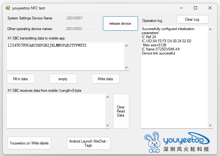
|Note: The I2C slave device address and communication rate need to be set and modified in the motherboard ASL CODE
Operation process:
- Connect I2C device first:Click "Connecting I2C devices"button
- Fill in the register address. Some devices have a register address of 1 byte, while others have a register address of 2 bytes, depending on the specific I2C device
- Can perform read and write operations
The USB to I2C slave module can be used to simulate the I2C slave, as shown in the figure:
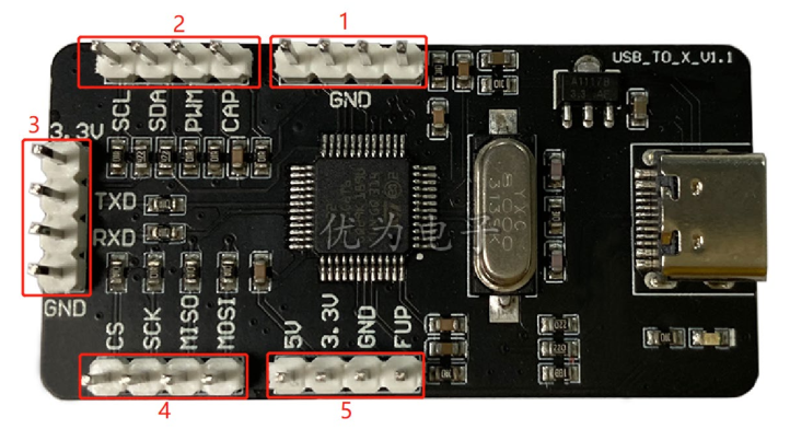
The module is connected to the computer USB, and the I2C related pins and development connections are as follows:
| Main board J2301 interface wire sequence | Purpose | Analog module labeling 1 and 2 |
|---|---|---|
| 1 | 3V3 | Not connected: because the module has been powered on and does not need to be connected to the power supply of the development board |
| 2 | I2C3_ SCL | SCL |
| 3 | I2C3_ SDA | SDA |
| 4 | GND | GND |
Configure the software on the computer, as shown in the parameter section on the left side of the figure: Set USB to I2C slave mode, address bits: 7, address is 50, test register is written as 00, and then click "Set Parameter"
The device address 50 here should be consistent with the I2C slave device address described in the motherboard ASL CODE
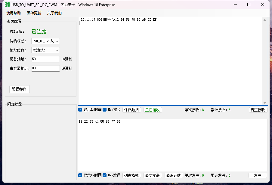
The development version of I2C testing software, after connecting to the I2C device, click "Write Data to Register", so that the software simulating the I2C slave will display the data received from the development version.
Next, in the development version of I2C testing software, click "Read Register Data" and you will see the data read from the simulated I2C slave module on the I2C testing software interface
Note: PC simulation software, set to I2C slave, is equivalent to simulating an I2C storage device. It is necessary to first write content to the register address and then read out the same content. Otherwise, it may be other values
6 in 1 USB Adapter Module Purchase Link Click here
Test software download
Execution File(Right Mouse Menu -> Save As)
driver(Right Mouse Menu -> Save As)
Download testing software source code
Source Code(Right Mouse Menu -> Save As)