¶ LED light control demonstration
1、 Hardware Description:
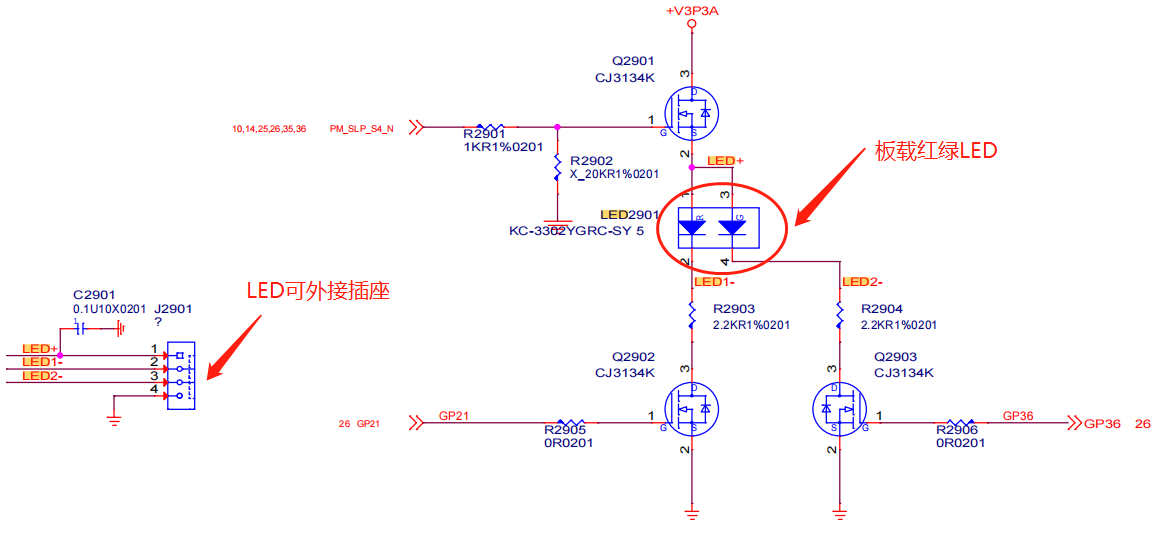
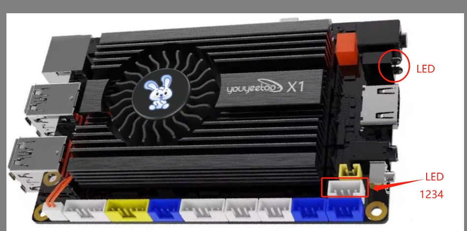
The J2901 socket on the motherboard is an LED external socket, and the circuit is connected to the onboard LED2901. We need to use the inpoutx64 library for LED operation


2、 Control method:
LED control is the control of the onboard SUPER IO chip, which is based on the chip communication protocol
Description of LED control address and control method
| LED | Control register (addr) | State control (ctrlCode) |
|---|---|---|
| Red LED | 0XB1 | 0X00 on, 0X02 off |
| Green LED | 0XC2 | 0X00 on, 0X40 off |
| Red LED breathing effect | 0XF8 | 0X00 on, 0X11 off |
| Green LED breathing effect | 0XF8 | 0X00 on, 0X1E off |
3、Core Control Code:
//Addr LED control register, ctrlCode control mode
bool Led_Ctrl00(byte addr, byte ctrlCode)
{
   if (idOK())
   {
   	//SUPER IO芯片进入模式
   	SetPortVal(0x2E, 0x87, 1);
   	SetPortVal(0x2E, 0x01, 1);
   	SetPortVal(0x2E, 0x55, 1);
   	SetPortVal(0x2E, 0x55, 1);

   	//选择LED设备
   	SetPortVal(0x2E, 0x07, 1);
   	SetPortVal(0x2F, 0x07, 1);

   	//控制LED状态
   	SetPortVal(0x2E, addr, 1);
   	SetPortVal(0x2F, ctrlCode, 1);

   	//SUPER IO芯片退出模式
   	SetPortVal(0x2E, 0x02, 1);
   	SetPortVal(0x2F, 0x02, 1);
   	return true;
   }
   return false;
}
4、 Instructions for using sample software control:
Regarding LED testing samples, a C # sample program with inpoutx64 operating code will be provided

Testing software usage
Click on the checkbox on the software to observe the corresponding LED status changes
Test software download:
Execution File
Download testing software source code:
Source Code