Complete GPIO control tutorial based on youyeetoo K1, including LED and buzzer control examples
¶ K1 GPIO Pins
This board provides 17 GPIO pins, divided into two categories:
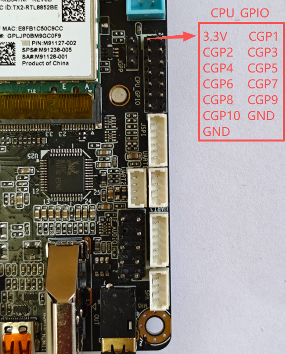
CPU GPIO (10 pins)
- Access PCH chipset GPIO via memory mapping
- Pins:
CGP1,CGP3,CGP5,CGP7,CGP9-> (Voltage range: 0 ~ 3.3V)
CGP2,CGP4,CGP6,CGP8,CGP10-> (Voltage range: 0 ~ 1.8V)
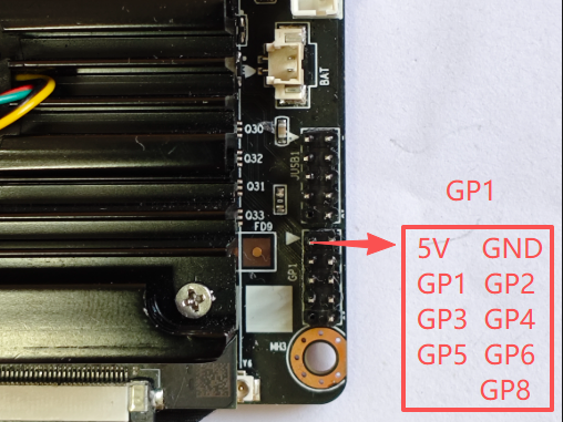
Super I/O GPIO (7 pins)
- Access Super I/O chip GPIO via I/O ports
- Pins:
GP1, GP2, GP3, GP4, GP5, GP6, GP8-> (Voltage range: 0 ~ 3.3V)
¶ Hardware Connection Example
This tutorial uses an integrated module containing 3 LEDs and 1 buzzer, with built-in current limiting resistors and driver circuits.
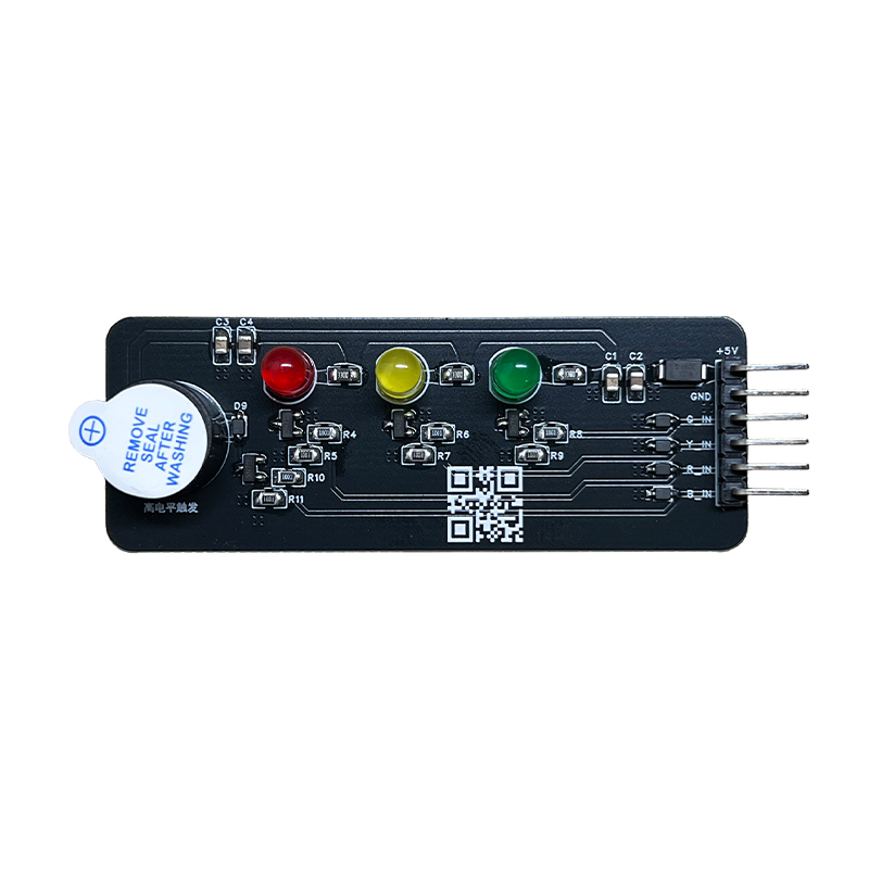
Module Wiring:
| Module Pin | Connect to | Description |
|---|---|---|
| 5V | Power 5V | Power supply |
| GND | Power GND | Ground |
| G_IN | GPIO Pin | Green LED control |
| Y_IN | GPIO Pin | Yellow LED control |
| R_IN | GPIO Pin | Red LED control |
| B_IN | GPIO Pin | Buzzer control |
Example Wiring Scheme:
5V   ──→ 5V Power
GND  ──→ GND
G_IN ──→ CGP1 (Green LED)
Y_IN ──→ CGP5 (Yellow LED)
R_IN ──→ CGP9 (Red LED)
B_IN ──→ CGP3 (Buzzer)
Control Method:
- High level (high): LED on / Buzzer on
- Low level (low): LED off / Buzzer off
¶ Software Operation
¶ System Environment
Test environment for this tutorial:
- Operating System: Ubuntu 20.04
- Kernel Version: 5.15.0-139-generic
- GCC Version: 9.4.0
Permission Requirements:
- Root permission required (for loading driver and accessing hardware)
Note: Other Linux distributions should work in theory, but have not been tested
¶ Development Tools
Note: Internet connection required for download and installation
Install necessary compilation tools:
# Update package list (requires internet)
sudo apt update

# Install compilation toolchain (includes gcc, g++, make, etc.)
sudo apt install build-essential

# Install kernel headers (for compiling driver)
sudo apt install linux-headers-$(uname -r)
Verify installation:
# Check gcc version
gcc --version

# Check make version
make --version
Note: build-essential includes gcc, g++, make and other compilation tools, install once.
¶ Quick Start
- Download the project package to your Ubuntu environment
Youyeetoo Official Download Link
http://dd.youyeetoo.cn:5000/sharing/7ikoBs9OD
¶ 0. Extract Project Files
# Extract the archive
test@test-K1-SBC:~$ unzip K1linux-gpio.zip
Archive:  K1linux-gpio.zip
   creating: linux-gpio/
  inflating: linux-gpio/alarm_system.sh
  inflating: linux-gpio/buzzer_test.sh
   creating: linux-gpio/drv/
  inflating: linux-gpio/drv/.module-common.o
  inflating: linux-gpio/drv/fhl_x86gpio_drv.c
 extracting: linux-gpio/drv/fhl_x86gpio_drv.mod
  inflating: linux-gpio/drv/Makefile
  inflating: linux-gpio/IOApp.cpp
  inflating: linux-gpio/IOApp.h
  inflating: linux-gpio/led_blink.sh
  inflating: linux-gpio/led_flow.sh
  inflating: linux-gpio/LinuxGPIO.cpp
  inflating: linux-gpio/LinuxGPIO.h
  inflating: linux-gpio/Makefile
  inflating: linux-gpio/README.md
  inflating: linux-gpio/README_CN.md
  inflating: linux-gpio/setup.sh
  inflating: linux-gpio/test_gpio.cpp

# Enter project directory
cd linux-gpio
¶ 1. Compile Driver and Program
# Grant execution permission to all scripts
chmod +x *.sh

# One-click compilation
test@test-K1-SBC:~$ ./setup.sh
========================================
  GPIO Project Setup
========================================
...
========================================
✓ Setup completed!
========================================

Generated files:
  • fhl_x86gpio_drv.ko   - Kernel driver module
  • test_gpio            - GPIO control program

Next steps:
  1. Load driver:
     sudo insmod fhl_x86gpio_drv.ko

  2. Test GPIO:
     sudo ./test_gpio CGP1 out high

  3. Run scripts:
     sudo ./led_blink.sh

To unload driver:
  sudo rmmod fhl_x86gpio_drv

Available scripts:
  • led_blink.sh      - LED blink test
  • led_flow.sh       - Flow light effect
  • buzzer_test.sh    - Buzzer test
  • alarm_system.sh   - Alarm system demo

========================================
After successful compilation, the following will be generated:
fhl_x86gpio_drv.ko- Kernel driver moduletest_gpio- GPIO control program
¶ 2. Load Driver
# Load driver (requires root permission)
test@test-K1-SBC:~/linux-gpio$ sudo insmod fhl_x86gpio_drv.ko
[sudo] password for test:

# Verify driver loaded successfully
test@test-K1-SBC:~/linux-gpio$ lsmod | grep fhl_x86gpio_drv
fhl_x86gpio_drv        12288  0

# Check device file
test@test-K1-SBC:~/linux-gpio$ ls -l /dev/fhlx86gpio
crw------- 1 root root 10, 122  Sep  9 16:17 /dev/fhlx86gpio
¶ 3. Test GPIO
# Set CGP1 to output high level
test@test-K1-SBC:~/linux-gpio$ sudo ./test_gpio CGP1 out high
GPIO Open Success
SUCCESS: CGP1 set to output HIGH

# Set CGP1 to output low level
test@test-K1-SBC:~/linux-gpio$ sudo ./test_gpio CGP1 out low
GPIO Open Success
SUCCESS: CGP1 set to output LOW

# Read CGP9 input status
test@test-K1-SBC:~/linux-gpio$ sudo ./test_gpio CGP9 in
GPIO Open Success
read cpu io,ret=0X800102
SUCCESS: CGP9 input level: HIGH (1)
¶ test_gpio Program Usage
¶ Basic Syntax
sudo ./test_gpio <pin_name> <mode> [level]
¶ Parameter Description
- pin_name:
CGP1-CGP10orGP1-GP6, GP8 - mode:
out- Output modein- Input mode
- level (required for output mode only):
high- High levellow- Low level
¶ Usage Examples
# Output mode
sudo ./test_gpio CGP1 out high    # CGP1 output high level
sudo ./test_gpio CGP2 out low     # CGP2 output low level
sudo ./test_gpio GP3 out high     # GP3 output high level

# Input mode
sudo ./test_gpio CGP9 in          # Read CGP9 input status
sudo ./test_gpio GP2 in           # Read GP2 input status
¶ Example Script Usage
The project provides 4 ready-to-use example scripts, with default configuration corresponding to the above wiring scheme:
¶ 1. LED Blink Test
sudo ./led_blink.sh
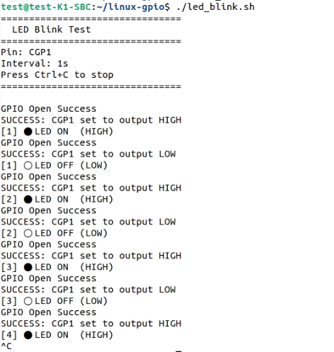
Function: Uses CGP1 pin by default, can be changed to any LED input of the module (G_IN/Y_IN/R_IN)
Configurable Parameters (edit script to modify):
PIN="CGP1"- Change to corresponding GPIO pin (e.g.,CGP2,CGP3, etc.)INTERVAL=1- Change blink interval (seconds)
¶ 2. Flow Light Effect
sudo ./led_flow.sh
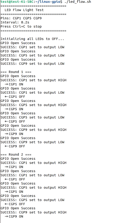
Function: 3 LEDs (G_IN, Y_IN, R_IN) light up sequentially
Default Configuration:
PINS=("CGP1" "CGP5" "CGP9")- Corresponds to G_IN, Y_IN, R_ININTERVAL=0.2- Flow speed (seconds)
¶ 3. Buzzer Test
sudo ./buzzer_test.sh
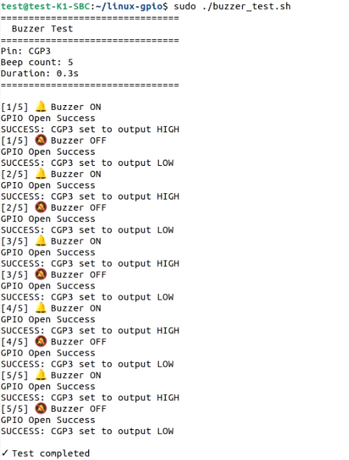
Function: Buzzer (B_IN) beeps 5 times
Default Configuration:
PIN="CGP3"- Corresponds to B_INBEEP_COUNT=5- Number of beepsBEEP_DURATION=0.3- Beep duration (seconds)BEEP_INTERVAL=0.3- Beep interval (seconds)
¶ 4. Alarm System Demo
sudo ./alarm_system.sh
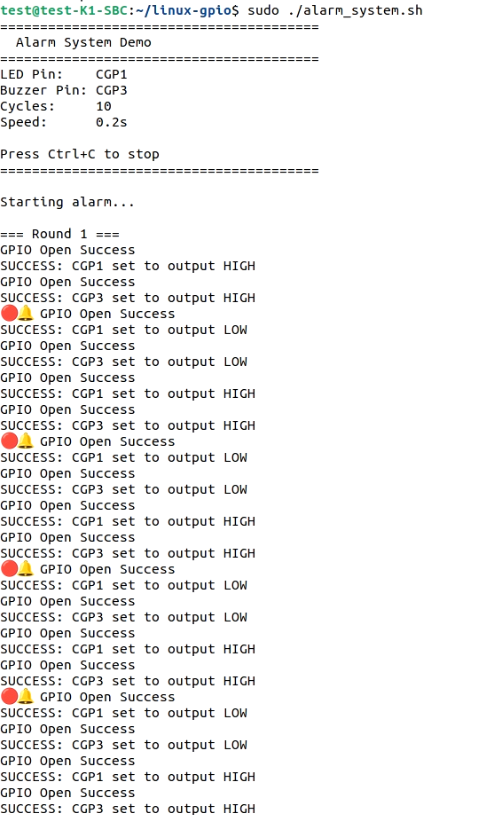
Function: LED (R_IN) and buzzer (B_IN) flash/beep synchronously, looping playback
Default Configuration:
LED_PIN="CGP1"- Can be changed toCGP9(R_IN)BUZZER_PIN="CGP3"- Corresponds to B_INALARM_CYCLES=10- Number of alarm cycles per roundALARM_SPEED=0.2- Alarm speed (seconds)
Stop Script: Press Ctrl+C
¶ FAQ
¶ Q1: "ERROR: GPIO driver not loaded"
Cause: Driver not loaded
Solution:
sudo insmod fhl_x86gpio_drv.ko
¶ Q2: "Failed to open GPIO driver"
Cause: Insufficient permissions
Solution: Run command with sudo
sudo ./test_gpio CGP1 out high
¶ Q3: LED not lighting
Checklist:
- Is the module properly powered (5V and GND)?
- Is the GPIO pin connected to the correct module input (G_IN/Y_IN/R_IN)?
- Did the command execute successfully (see "SUCCESS" message)?
- Did you use
sudo?
¶ Q4: Buzzer not sounding
Checklist:
- Is the module properly powered (5V and GND)?
- Is the GPIO pin connected to B_IN?
- Is the module itself working properly (test by connecting B_IN directly to 5V with jumper wire)?
- Did the command execute successfully (see "SUCCESS" message)?
¶ Q5: How to unload driver
# Unload driver
sudo rmmod fhl_x86gpio_drv

# Check if unloaded successfully
lsmod | grep fhl_x86gpio_drv