¶ GPIO Development(Linux)
I. Hardware Description:
The motherboard features two sets of programmable GPIOs: one directly connected to the CPU (CPU_GPIO), and the other accessible via the SIO chip
The following are the I/O pins connected to the CPU, with the PCB silk-screen number: CPU_GPIO
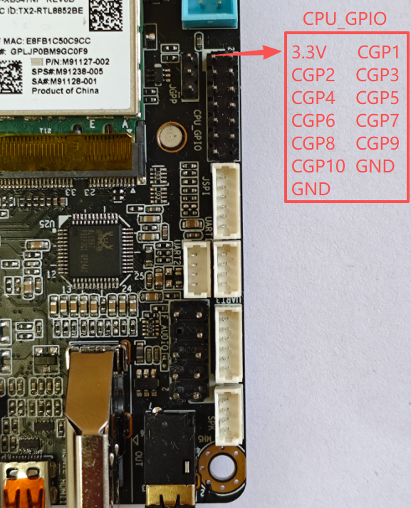
| CPUIO | Address of the corresponding operation | Voltage range (V) |
|---|---|---|
| CGP1 | 0XFD6A0A90 | 0--3.3V |
| CGP3 | 0XFD6D0A60 | 0--3.3V |
| CGP5 | 0XFD6D0A70 | 0--3.3V |
| CGP7 | 0XFD6D0A40 | 0--3.3V |
| CGP9 | 0XFD6D0A50 | 0--3.3V |
| CGP2 | 0XFD6D0710 | 0--1.8V |
| CGP4 | 0XFD6D0B70 | 0--1.8V |
| CGP6 | 0XFD6D0720 | 0--1.8V |
| CGP8 | 0XFD6D0730 | 0--1.8V |
| CGP10 | 0XFD6D0700 | 0--1.8V |
The following are the printed I/O ports of the SIO chip, PCB silkscreen number: GP1
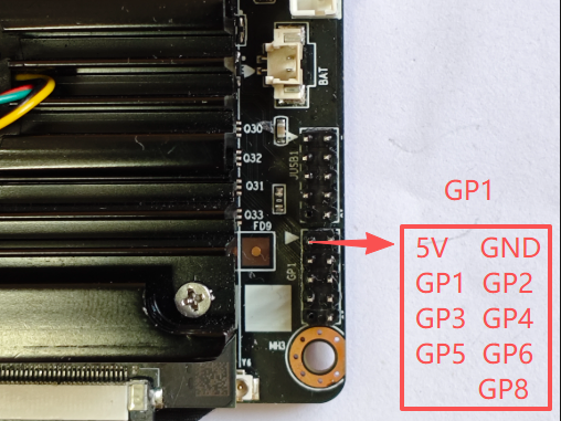
| SIO | bit address | Voltage range (V) | notes |
|---|---|---|---|
| GP1 | 0 | 0--3.3V | Supports up to 5V input |
| GP2 | 1 | 0--3.3V | Supports up to 5V input |
| GP3 | 2 | 0--3.3V | Supports up to 5V input |
| GP4 | 3 | 0--3.3V | Supports up to 5V input |
| GP5 | 4 | 0--3.3V | Supports up to 5V input |
| GP6 | 5 | 0--3.3V | Supports up to 5V input |
| GP8 | 7 | 0--3.3V | Supports up to 5V input |
2.Download testing software (kernel mapping driver mode):
Download the source code of Linux GPIO testing software:
linux-gpio-test-src-File
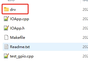
Source code directory structure description:
| File/Folder | Description |
|---|---|
| DRV folder | GPIO kernel mapping driver |
| IOApp. h | gpio application interface header file |
| IOApp. cpp | gpio application interface source file |
| Test_ Gpio. cpp | Test code main |
| Makefile | Make Compilation Script File |
| Readme. txt | Compilation process description file |
The compilation and operation process is as follows. The starting directory is linux-gpio
Before performing the compilation operation, it is necessary to first install the basic compilation tools. Please refer to the instructions in "Linux Application Development (Calling Hardware)" for the installation method.
#Enter the gpio driver source directory
user@K1:~/linux-gpio$  cd  drv

#Compile GPIO driver
user@K1:~/linux-gpio/drv$  make

#Return to the previous level directory
user@K1:~/linux-gpio/drv$  cd  ..

#Copy the driver ko to the current directory
user@K1:~/linux-gpio$  cp  drv/gpio_drv.ko   ./

#Compiling GPIO Test Applications
user@K1:~/linux-gpio$  make

#Execute program program
user@K1:~/linux-gpio$  sudo ./test_gpio
If there are no errors in the above operation, the test results will be displayed as follows:
$sudo ./test_gpio
GPIO Open Success
read cpu io,ret=0X800102
The CPU Gpio Output Is Successful The Led Control Is Successful And The K1_CPU_GPIO_CGP9 Input Level Is Successful:1
The SIO Output Is Successful The Led Control Is Successful And The SIO 5 Input Level Is Successful:1
Special reminder: Because it is controlling hardware, sudo is required to run the test program. If it is a root account, it can be run directly
3. GPIO application interface (kernel mapping driver method) description:
3.1 The following is a description of the structure of the IOApp. h file
#ifndef _IOAPP_H
#define _IOAPP_H

#include <stdint.h>
#include "LinuxGPIO.h"

#define K1_CPU_GPIO_CGP1 0XFD6A0A90
#define K1_CPU_GPIO_CGP2 0XFD6D0710
#define K1_CPU_GPIO_CGP3 0XFD6D0A60
#define K1_CPU_GPIO_CGP4 0XFD6D0B70
#define K1_CPU_GPIO_CGP5 0XFD6D0A70
#define K1_CPU_GPIO_CGP6 0XFD6D0720
#define K1_CPU_GPIO_CGP7 0XFD6D0A40
#define K1_CPU_GPIO_CGP8 0XFD6D0730
#define K1_CPU_GPIO_CGP9 0XFD6D0A50
#define K1_CPU_GPIO_CGP10 0XFD6D0700


#define K1_SIO_Bit_GP1 0
#define K1_SIO_Bit_GP2 1
#define K1_SIO_Bit_GP3 2
#define K1_SIO_Bit_GP4 3
#define K1_SIO_Bit_GP5 4
#define K1_SIO_Bit_GP6 5
#define K1_SIO_Bit_GP7 6
#define K1_SIO_Bit_GP8 7

#define K1_SIO_REG_DIR 0xCE
#define K1_SIO_REG_VAL 0xA06

// Before Use You Need To Dynamically Load The Driver Load Module Method 1 Load This Module Only
// commandLine:  chmod 644  gpio_drv.ko
// commandLine:  insmod gpio_drv.ko
class IOApp
{
private:
        std::unique_ptr<LinuxGPIO> lpGpio;

public:
        IOApp();
        ~IOApp();
        void LoadGpioDriver();
        bool IsOpen();
public:
        // gpio Output High And Low Levels
        bool CpuIO_Set(uint32_t addr, bool hightLevel);
        // return: 0:low 1:hight 2:model error,-1:failed
        int32_t CpuIO_Get(uint32_t addr);

        // Set Gpio To Input Mode
        bool CpuIO_SetModel_InPut(uint32_t addr);
        // Set SIO  Output
        bool SIO_Set2(uint16_t bitOffset, bool isHight);
        // return: 0:low 1:hight 2:model error,-1:failed
        int32_t SIO_Get2(uint16_t bitOffset);
};

#endif
3.2 IO Input and Output Description:
3.2.1 The IO port has input mode and output mode
3.2.2 After setting the IO port to output mode, the high and low levels of the output are correct, and the IO values read in this mode are random.
3.2.3 After setting the IO port to input mode, the read value is:
If the reading value is 0X84000102, it indicates high level, and if the value is 0X84000100, it indicates low level
If other values are read out, it is possible that IO is not in input mode.
4. Explanation of other control methods for GPIO (refer to usage based on actual situation):
4.1 GPIO sysfs interface (kernel 4.8 has been disabled by default and is not recommended by the official)
In Linux, the most common way to read and write GPIO is to use the GPIO sysfs interface, which is achieved by operating on files such as export, unexport, gpio {N}/direction, and gpio {N}/value (replacing {N} with actual pin numbers) in the/sys/class/gpio directory. It often appears in shell scripts. Starting with kernel 4.8, support for libgpiod has been added; The original access method based on sysfs will gradually be abandoned.
4.2 Using the libgpiod library to control IO
Libgpiod is a character device interface, and GPIO access control is achieved by manipulating character device files (such as/dev/gpiodchip0). It provides command tools, c libraries, and Python encapsulation through libgpiod.
Note: The GPIO sysfs interface and libgpiod library can only control CPU-GPIO directly connected to the CPU, and do not support controlling GPIO exported from Super IO
5. GPIO test sample program Qt interface (kernel mapping driver mode):
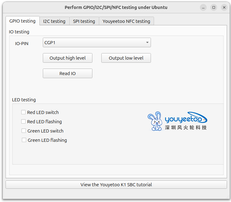
On the GPIO test page
IO PIO: You can choose to switch between 5 different GIPIOs
Output mode test:
Select the IO to be tested, first click on "Set Output Mode" and set the IO to output mode,
Input 1 (output high level) or 0 (output low level) in the "value (HEX)" position
Then click the "Write IO" button and use a multimeter to measure the corresponding IO to verify if the output level is correct
Input mode test:
Select the IO to be tested, first click on "Set Input Mode" and set the IO to input mode,
The corresponding IO can be connected to GND (low level) or suspended (IO internal pull-up, default high level)
Then click the "Read IO" button to view the read value (if the value is 0X84000102, it indicates high level, and if the value is 0X84000100, it indicates low level) to verify the read result
Please refer to the following page for sample source code and how to compile and use the QT interface of the testing program:
https://wiki.youyeetoo.com/en/youyeetooK1/linux/qt-build