¶ GPIO input/output operation
1.Hardware Description:
The motherboard features two sets of programmable GPIOs: one directly connected to the CPU (CPU_GPIO), and the other accessible via the SIO chip
The following are the I/O pins connected to the CPU, with the PCB silk-screen number: CPU_GPIO
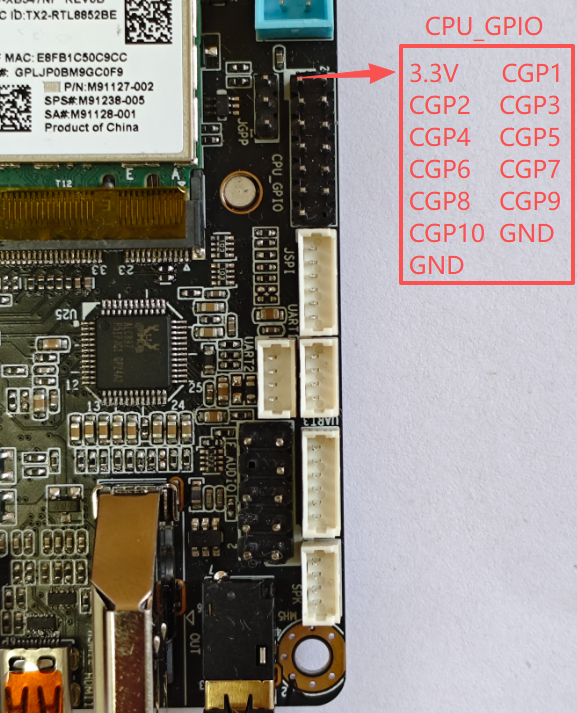
| CPUIO | Address of the corresponding operation | Voltage range (V) |
|---|---|---|
| CGP1 | 0XFD6A0A90 | 0--3.3V |
| CGP3 | 0XFD6D0A60 | 0--3.3V |
| CGP5 | 0XFD6D0A70 | 0--3.3V |
| CGP7 | 0XFD6D0A40 | 0--3.3V |
| CGP9 | 0XFD6D0A50 | 0--3.3V |
| CGP2 | 0XFD6D0710 | 0--1.8V |
| CGP4 | 0XFD6D0B70 | 0--1.8V |
| CGP6 | 0XFD6D0720 | 0--1.8V |
| CGP8 | 0XFD6D0730 | 0--1.8V |
| CGP10 | 0XFD6D0700 | 0--1.8V |
以下是SIO芯片印出来的IO口,PCB丝印编号:GP1
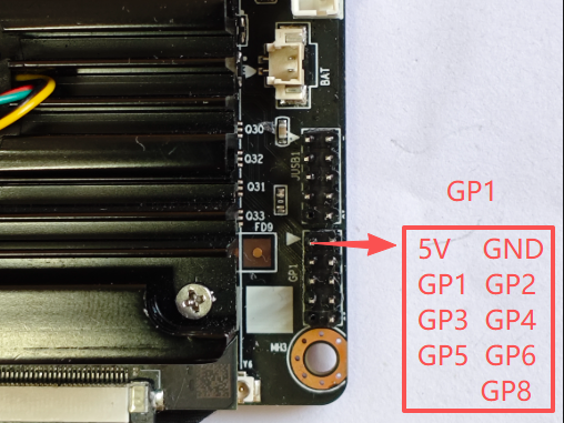
| SIO | bit address | Voltage range (V) | notes |
|---|---|---|---|
| GP1 | 0 | 0--3.3V | Supports up to 5V input |
| GP2 | 1 | 0--3.3V | Supports up to 5V input |
| GP3 | 2 | 0--3.3V | Supports up to 5V input |
| GP4 | 3 | 0--3.3V | Supports up to 5V input |
| GP5 | 4 | 0--3.3V | Supports up to 5V input |
| GP6 | 5 | 0--3.3V | Supports up to 5V input |
| GP8 | 7 | 0--3.3V | Supports up to 5V input |
2. GPIO mode setting and control:
¶ Control of CPU-GPIO:
It is necessary to switch modes by writing the following values to the corresponding GPIO through the inpoutx64 library. Write once and hold for a long time. After powering on the board again, restore it to the default output mode
Output high level: 0x00800201
Output low level: 0x00800200
Switch input mode: 0x00800100
When IO is in output mode: writing 1 to the corresponding GPIO indicates high level, writing 0 indicates low level (Note that in output mode, the value of IO read at this time is random, please ignore this value)
When IO is in input mode: Read the corresponding GPIO. If the value is 0X800102, it indicates a high level; if the value is 0X800100, it indicates a low level (Note that in input mode, do not write data to IO. Once data is written, the IO will switch to output mode)
For the above operation details, the sample program has been encapsulated and can be used directly
¶ Control of SIO
By using the inpoutx64 library and following the SIO chip operation process, the sample program has been encapsulated and can be used directly
3.Instructions for using sample software control:
Regarding GPIO test samples, we will provide a C # sample program with inpoutx64 operation code
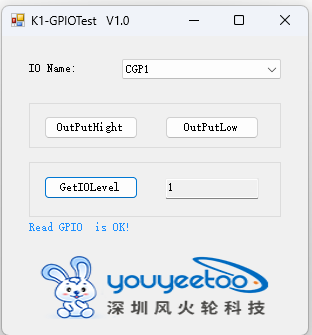
Testing software usage
Select the IO to be tested
Output High Level: The IO selected for operation outputs a high level
Output low level: The IO selected for operation outputs a low level
Read IO level: Set IO to input mode and read the current IO level. The obtained values are: 0 for low level, 1 for high level, 2 for failure and exception
Test software download:
Execution File
Test software source code download:
Source Code