¶ Build development environment
¶ install Android Studio
- Go to the Android developer website
- double-click
android-studio-2022.1.1.19-windows.exeOperation and installation
¶ Create system app demo
一、 Create the project as shown in the GIF below。

二、Add a system signature file
- In the project directory, create a security folder to store the system signature file.
- Store the system signature file 'YY3568.keystore' linked below in the security folder.
- Click 'File' -> 'Project Structure...
->Modules->Signing Configs` - Click '+' under 'Signing Configs', type' YY3568 'and press enter. Information to fill in at the appropriate location.
- 'Store File' : Click the folder icon to select the path where YY3568.keystore is stored
- 'Store Password' : Enter youyeetoo
- 'Key Alias' : Enter youyeetoo
- 'Key Password' : Enter youyeetoo
- Click 'Build Variants' ->' Build Types' -> 'debug' -> 'Signing Config'. Select '$signingConfigs.YY3568'. The GIF is shown below.

3、Add system permissions
Add it in the 'AndroidManifest.xml' file
android:sharedUserId="android.uid.system"
android:sharedUserMaxSdkVersion="32"

-
Add framework.jar
-
Download the source code (on Ubuntu host)
- Unzip the source code (on Ubuntu host)
cat YY3568-Android11.tar.gz0* > YY3568-Android11.tar.gz
tar -xzvf YY3568-Android11.tar.gz
- Compile (on Ubuntu host)
cd YY3568-Android11
source build/envsetup.sh
lunch YY3568-userdebug
./build.sh -UKAu
- Package 'framework.jar' (on Ubuntu host)
make javac-check-framework
End of the packaging, generate out/target/common/obj/JAVA_LIBRARIES/framework_intermediates/classes. Jar file. Copy the classes.jar file to the app/libs directory in the project directory.
- Add classes.jar to the Android library
- Switch to the Project view.
- Right-click app/libs/classes.jar. Select 'Add As Library... `

- Modify build.gradle in the app directory.
will
dependencies {
    ...
    implementation files('libs\\classes.jar')
    ...
}

be refitted into

dependencies {
    ...
    compileOnly files('libs\\classes.jar')
    ...
}
¶ Program runtime environment
¶ Run on the development board
¶ GPIO call instance
GPIO: General-Purpose Input/Output (GPIO) is a universal pin that can be dynamically configured and controlled during software operation.
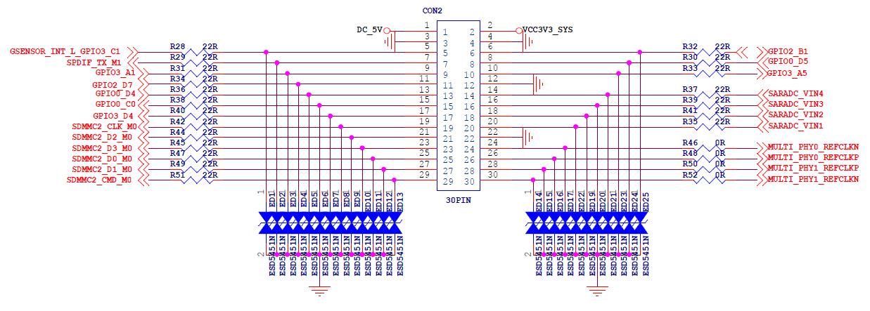
YY3568 pin classification
- Power pin: 5V, 3.3V, GND(Ground)
- Regular GPIO control pins: These pins can be programmed to dynamically control the output high and low levels, and can also be used to read the input high and low level values.
- Reusability GPIO pin: Not only as an ordinary GPIO port, it can be used to achieve I2C,SPI,UART communication,PWM output and other functions.
YY3568 has thirty GPIO ports open to the public, as shown below

¶ Introduction to GPIO programming development
- There are a variety of ways to implement GPIO programming, and our more conventional way is to achieve the control of GPIO port through sysfs.
- If we need sysfs to implement GPIO port control, we first need support from the underlying kernel. The current source code is supported by sysfs gpio control.
- After the system is running properly, we can enter the system with adb shell command and see the sysfs controlled interface under /sys/class/gpio. There are three types of interfaces, namely control interface, GPIO signal and GPIO controller. This part can be reference in the source (kernel/Documentation/gpio sysfs. TXT)
YY3568:/ # ls -l /sys/class/gpio/
total 0
--w------- 1 root root 4096 2023-01-16 11:01 export
lrwxrwxrwx 1 root root    0 2023-01-16 11:01 gpiochip0 -> ../../devices/platform/fdd60000.gpio/gpio/gpiochip0
lrwxrwxrwx 1 root root    0 2023-01-16 11:01 gpiochip128 -> ../../devices/platform/fe770000.gpio/gpio/gpiochip128
lrwxrwxrwx 1 root root    0 2023-01-16 11:01 gpiochip32 -> ../../devices/platform/fe740000.gpio/gpio/gpiochip32
lrwxrwxrwx 1 root root    0 2023-01-16 11:01 gpiochip511 -> ../../devices/platform/fdd40000.i2c/i2c-0/0-0020/rk805-pinctrl/gpi
o/gpiochip511
lrwxrwxrwx 1 root root    0 2023-01-16 11:01 gpiochip64 -> ../../devices/platform/fe750000.gpio/gpio/gpiochip64
lrwxrwxrwx 1 root root    0 2023-01-16 11:01 gpiochip96 -> ../../devices/platform/fe760000.gpio/gpio/gpiochip96
--w------- 1 root root 4096 2023-01-16 11:01 unexport
¶ GPIO number calculation mode
Each chip can have N groups of GPIOs, each group of GPIOs has a maximum of 32 GPIOs. Therefore, each chip has a maximum of N*32 GPIO ports.
In our YY3568, the GPIO port is defined in this way.
GPIO0_A0~GPIO0_A7 GPIO0_B0~GPIO1_B7 .... GPIO0_D0~GPIO1_D7
GPIO1_A0~GPIO1_A7 .....
GPIO2_A0~GPIO2_A7 .....
GPIO3_A0~GPIO3_A7 .....
GPIO4_A0~GPIO4_A7 .....
It is not difficult to find that the rule A0~D7 means that there are 4*8=32 GPIOs in a group
We can easily calculate that GPIO0_D4 in the pin diagram corresponds to gpio28 through this law
¶ (1)control interface
The control interface mainly refers to the two interfaces /sys/class/gpio/export and /sys/class/gpio/unexport in the above figure. The user mode can control GPIO through these two interfaces.
- /sys/class/gpio/export Implementation exports GPIO control from kernel space to user space
- /sys/class/gpio/unexport Used to cancel the export of GPIO control from kernel space to user space.
example
// Access adb requires root permission

D:\code\ThinkerEdgeR\adb>adb root && adb remount && adb shell

remount succeeded

// Go to the gpio directory

YY3568:/ # cd /sys/class/gpio

// View files in the directory

YY3568:/sys/class/gpio # ls

export gpiochip0 gpiochip128 gpiochip32 gpiochip511 gpiochip64 gpiochip96 unexport

// Export gpio28 from kernel space back to user space

YY3568:/sys/class/gpio # echo 28 > export

// An additional gpio28 directory is found

YY3568:/sys/class/gpio # ls

export gpio28 gpiochip0 gpiochip128 gpiochip32 gpiochip511 gpiochip64 gpiochip96 unexport

// Unexport GPIO control from kernel space to user space for GPIO number 28

YY3568:/sys/class/gpio # echo 28 > unexport

// Checking the directory again, gpio28 has been removed

YY3568:/sys/class/gpio # ls
export gpiochip0 gpiochip128 gpiochip32 gpiochip511 gpiochip64 gpiochip96 unexport
// Note: If export fails, the AP side (kernel, etc.) is in use. If the value cannot be changed (as shown in the following code), the BP side (modem) is in use.
¶ (2)GPIO signal
The GPIO signal is the GPIO itself. This corresponds to /sys/class/gpio/gpioN/, which has multiple properties. We can control the GPIO port by controlling these attributes.
- "direction" property: Read the value of "in" or "out". The GPIO can be set as input or output by writing "in" or "out" to the property. If you write "out" directly, it will make the GPIO output low directly. You can also set the output low or high level directly by writing "low" or "high".
- "value" attribute, used to read the input level or control the output level. If GPIO is output, writing 0 to value is output low, and writing non-0 is output high. If it is set as input, reading 0 indicates that the input is low and 1 is high.
- "edge" property, which is used to set the trigger level and only appears if GPIO can be set to interrupt the input pin.
YY3568:/sys/class/gpio # cd gpio28
YY3568:/sys/class/gpio/gpio28 # ls
active_low  device  direction  edge  power  subsystem  uevent  value
¶ (3)GPIO controller
GPIO controller, used to represent the initial GPIO of GPIO control implementation, the path for the/sys/class/GPIO gpiochipN /. Such as the/sys/class/gpio/gpiochip0 / said gpio controller initialization code is 0. The properties of the GPIO controller are read-only, including base, label, and ngpio.
-
The "base" attribute, which has the same meaning as the N in gpiochipN, indicates the first GPIO implemented by this group of GPIO controllers.
-
"ngpio" property, which indicates the number of GPIOs supported by the controller. The supported GPIOs are numbered from N to N+ NGPIO-1
-
The "label" attribute, used to determine the controller, is not always unique
YY3568:/sys/class/gpio/gpiochip0 # ls
base  device  label  ngpio  power  subsystem  uevent
¶ View all GPIO information
1|YY3568:/sys/class/gpio/gpiochip0 # cat /sys/kernel/debug/pinctrl/pinctrl-rockchip-pinctrl/pinmux-pins
Pinmux settings per pin
Format: pin (name): mux_owner gpio_owner hog?
pin 0 (gpio0-0): (MUX UNCLAIMED) (GPIO UNCLAIMED)
pin 1 (gpio0-1): (MUX UNCLAIMED) (GPIO UNCLAIMED)
pin 2 (gpio0-2): 0-0020 (GPIO UNCLAIMED) function pmic group soc_slppin_gpio
pin 3 (gpio0-3): (MUX UNCLAIMED) (GPIO UNCLAIMED)
pin 4 (gpio0-4): fe2b0000.dwmmc (GPIO UNCLAIMED) function sdmmc0 group sdmmc0-det
pin 5 (gpio0-5): vcc5v0-otg-regulator gpio0:5 function usb group vcc5v0-otg-en
pin 6 (gpio0-6): (MUX UNCLAIMED) (GPIO UNCLAIMED)
pin 7 (gpio0-7): (MUX UNCLAIMED) (GPIO UNCLAIMED)
pin 8 (gpio0-8): (MUX UNCLAIMED) (GPIO UNCLAIMED)
pin 9 (gpio0-9): fdd40000.i2c (GPIO UNCLAIMED) function i2c0 group i2c0-xfer
pin 10 (gpio0-10): fdd40000.i2c (GPIO UNCLAIMED) function i2c0 group i2c0-xfer
pin 11 (gpio0-11): fe5a0000.i2c (GPIO UNCLAIMED) function i2c1 group i2c1-xfer
pin 12 (gpio0-12): fe5a0000.i2c (GPIO UNCLAIMED) function i2c1 group i2c1-xfer
pin 13 (gpio0-13): (MUX UNCLAIMED) (GPIO UNCLAIMED)
pin 14 (gpio0-14): (MUX UNCLAIMED) (GPIO UNCLAIMED)
pin 15 (gpio0-15): (MUX UNCLAIMED) (GPIO UNCLAIMED)
pin 16 (gpio0-16): (MUX UNCLAIMED) gpio0:16
pin 17 (gpio0-17): (MUX UNCLAIMED) (GPIO UNCLAIMED)
pin 18 (gpio0-18): (MUX UNCLAIMED) (GPIO UNCLAIMED)
pin 19 (gpio0-19): (MUX UNCLAIMED) (GPIO UNCLAIMED)
pin 20 (gpio0-20): (MUX UNCLAIMED) (GPIO UNCLAIMED)
pin 21 (gpio0-21): (MUX UNCLAIMED) (GPIO UNCLAIMED)
pin 22 (gpio0-22): fe6e0030.pwm (GPIO UNCLAIMED) function pwm7 group pwm7-pins
pin 23 (gpio0-23): (MUX UNCLAIMED) (GPIO UNCLAIMED)
pin 24 (gpio0-24): fiq-debugger (GPIO UNCLAIMED) function uart2 group uart2m0-xfer
pin 25 (gpio0-25): fiq-debugger (GPIO UNCLAIMED) function uart2 group uart2m0-xfer
pin 26 (gpio0-26): (MUX UNCLAIMED) (GPIO UNCLAIMED)
pin 27 (gpio0-27): (MUX UNCLAIMED) (GPIO UNCLAIMED)
pin 28 (gpio0-28): (MUX UNCLAIMED) gpio0:28
...
¶ The SHELL calls GPIO
You need to log in to the Android system through adb and switch root permissions.
Connect YY3568 to your computer using a dual female USB cable, start adb command window, and enter the following command:
 $ adb root
 $ adb remount
 $ adb shell
- The gpio device directory is displayed
YY3568:/ # cd /sys/class/gpio
YY3568:/sys/class/gpio # ls
export  gpio28  gpiochip0  gpiochip128  gpiochip32  gpiochip511  gpiochip64  gpiochip96  unexport
- If there is no gpio directory you want to control, enter the following command to generate it
YY3568:/sys/class/gpio # echo 28 > export //28 Stands for gpio number
- Go to the corresponding gpio directory
YY3568:/sys/class/gpio # cd gpio28/
- View the current gpio status
YY3568:/sys/class/gpio/gpio28 # cat direction
out
- Change the gpio status to Input
YY3568:/sys/class/gpio/gpio28 # echo in > direction
YY3568:/sys/class/gpio/gpio28 # cat direction	// Check the gpio port status
 in
YY3568:/sys/class/gpio/gpio28 # cat value
 0					// 0 Indicates that low level is read. 1 indicates that high level is read
- Example Change the gpio status to Output
YY3568:/sys/class/gpio/gpio28 # echo out > direction
YY3568:/sys/class/gpio/gpio28 # cat direction	// Check the gpio port status
 out
YY3568:/sys/class/gpio/gpio28 # echo 1 > value  //1 Indicates high output level 0 indicates low output level
¶ C language calls GPIO
#include <stdio.h>
#include <stdlib.h>
#include <string.h>
#include <fcntl.h>
#include <unistd.h>
#include <sys/select.h>
#include <sys/stat.h>

#define GPIO_PIN 28

typedef enum {
    GPIO_OUTPUT = 1,
    GPIO_OUTPUT_HIGH,
    GPIO_OUTPUT_LOW,
    GPIO_INPUT,
} GPIO_DIRECT;

int gpio_direction(int gpio, int dir)
{
    int ret = 0;
    char buf[128];
    sprintf(buf, "/sys/class/gpio/gpio%d/direction", gpio);
    int gpiofd = open(buf, O_WRONLY);
    if(gpiofd < 0) {
        perror("Couldn't open IRQ file");
        ret = -1;
    }

    if(dir == GPIO_OUTPUT && gpiofd){
        if (3 != write(gpiofd, "out", 3)) {
            perror("Couldn't set GPIO direction to out");
            ret = -2;
        }
    }
    else if(dir == GPIO_OUTPUT_HIGH && gpiofd){
        if (4 != write(gpiofd, "high", 4)) {
            perror("Couldn't set GPIO direction to out high");
            ret = -3;
        }
    }
    else if (dir == GPIO_OUTPUT_LOW && gpiofd){
        if (3 != write(gpiofd, "low", 3)){
            perror("Couldn't set GPIO direction to out low");
            ret = -4;
        }
    }
    else if(gpiofd) {
        if(2 != write(gpiofd, "in", 2)) {
            perror("Couldn't set GPIO directio to in");
            ret = -5;
        }
    }

    close(gpiofd);
    return ret;
}

int gpio_set_edge(int gpio, int rising, int falling)
{
    int ret = 0;
    char buf[128];
    sprintf(buf, "/sys/class/gpio/gpio%d/edge", gpio);
    int gpiofd = open(buf, O_WRONLY);
    if(gpiofd < 0) {
        perror("Couldn't open IRQ file");
        ret = -1;
    }

    if(gpiofd && rising && falling) {
        if(4 != write(gpiofd, "both", 4)) {
            perror("Failed to set IRQ to both falling & rising");
            ret = -2;
        }
    } else {
        if(rising && gpiofd) {
            if(6 != write(gpiofd, "rising", 6)) {
                perror("Failed to set IRQ to rising");
                ret = -2;
            }
        } else if(falling && gpiofd) {
            if(7 != write(gpiofd, "falling", 7)) {
                perror("Failed to set IRQ to falling");
                ret = -3;
            }
        }
    }

    close(gpiofd);

    return ret;
}

int gpio_export(int gpio)
{
    int efd;
    char buf[50];
    int gpiofd, ret;

    /* Quick test if it has already been exported */
    sprintf(buf, "/sys/class/gpio/gpio%d/value", gpio);
    efd = open(buf, O_WRONLY);
    if(efd != -1) {
        close(efd);
        return 0;
    }

    efd = open("/sys/class/gpio/export", O_WRONLY);

    if(efd != -1) {
        sprintf(buf, "%d", gpio);
        ret = write(efd, buf, strlen(buf));
        if(ret < 0) {
            perror("Export failed");
            return -2;
        }
        close(efd);
    } else {
        // If we can't open the export file, we probably
        // dont have any gpio permissions
        return -1;
    }
    return 0;
}

void gpio_unexport(int gpio)
{
    int gpiofd, ret;
    char buf[50];
    gpiofd = open("/sys/class/gpio/unexport", O_WRONLY);
    sprintf(buf, "%d", gpio);
    ret = write(gpiofd, buf, strlen(buf));
    close(gpiofd);
}

int gpio_getfd(int gpio)
{
    char in[3] = {0, 0, 0};
    char buf[50];
    int gpiofd;
    sprintf(buf, "/sys/class/gpio/gpio%d/value", gpio);
    gpiofd = open(buf, O_RDWR);
    if(gpiofd < 0) {
        fprintf(stderr, "Failed to open gpio %d value\n", gpio);
        perror("gpio failed");
    }

    return gpiofd;
}

int gpio_read(int gpio)
{
    char in[3] = {0, 0, 0};
    char buf[50];
    int nread, gpiofd;
    sprintf(buf, "/sys/class/gpio/gpio%d/value", gpio);
    gpiofd = open(buf, O_RDWR);
    if(gpiofd < 0) {
        fprintf(stderr, "Failed to open gpio %d value\n", gpio);
        perror("gpio failed");
    }

    do {
        nread = read(gpiofd, in, 1);
    } while (nread == 0);
    if(nread == -1){
        perror("GPIO Read failed");
        return -1;
    }

    close(gpiofd);
    return atoi(in);
}

int gpio_write(int gpio, int val)
{
    char buf[50];
    int nread, ret, gpiofd;
    sprintf(buf, "/sys/class/gpio/gpio%d/value", gpio);
    gpiofd = open(buf, O_RDWR);
    if(gpiofd > 0) {
        snprintf(buf, 2, "%d", val);
        ret = write(gpiofd, buf, 2);
        if(ret < 0) {
            perror("failed to set gpio");
            return 1;
        }

        close(gpiofd);
        if(ret == 2) return 0;
    }
    return 1;
}


int gpio_select(int gpio)
{
    char gpio_irq[64];
    int ret = 0, buf, irqfd;
    fd_set fds;
    FD_ZERO(&fds);

    snprintf(gpio_irq, sizeof(gpio_irq), "/sys/class/gpio/gpio%d/value", gpio);
    irqfd = open(gpio_irq, O_RDONLY);
    if(irqfd < 1) {
        perror("Couldn't open the value file");
        return -13;
    }

    // Read first since there is always an initial status
    ret = read(irqfd, &buf, sizeof(buf));

    while(1) {
        FD_SET(irqfd, &fds);
        ret = select(irqfd + 1, NULL, NULL, &fds, NULL);
        if(FD_ISSET(irqfd, &fds))
        {
            FD_CLR(irqfd, &fds);  //Remove the filedes from set
            // Clear the junk data in the IRQ file
            ret = read(irqfd, &buf, sizeof(buf));
            return 1;
        }
    }
}

int main(int argc, char **argv)  {
    int gpio_pin = GPIO_PIN;

    gpio_export(gpio_pin);
    gpio_direction(gpio_pin, 1);

    for(int i = 0; i < 5; i++) {
        printf(">> GPIO %d ON\n", gpio_pin);
        gpio_write(gpio_pin, 1);

        sleep(1);

        printf(">> GPIO %d OFF\n", gpio_pin);
        gpio_write(gpio_pin, 0);

        sleep(1);
    }

    return 0;
}
¶ JAVA调用GPIO
1.New AndroidStdio project

2.选择Native C++
3.Define project name and package name (package name and project name can not be arbitrarily changed)

4.Select C++11 when C++ Standard is displayed on the next screen
5.The new project is shown in the figure. In the upper left corner, the mode can be switched to Project.

6.The required file name (CMakeLists.txt, MainActivity, activity_main.xml) exists after the project is created, and can be overwritten with the file with the same name as the attachment. test_gpio.c in the cpp file directory)

附件.zip
7.Run directly, you can download Scrcpy screen projection file for observation.
¶ CAN call instance
¶ CAN communication Introduction
CAN bus is a serial data communication protocol developed by German BOSCH company from the early 1980s to solve the data exchange between many control and test instruments in modern automobiles. It is a multi-master bus, and the communication medium can be twisted pair, coaxial cable or optical fiber.
The CAN transceiver used in YY3568 development board is TCAN1044V-Q1, which meets the physical layer requirements of ISO 11898-2:2016 high-speed CAN specification. The TCAN1044V-Q1 transceiver supports traditional CAN and CAN FD networks up to 8Mbps. The TCAN1044V-Q1 includes internal logic level conversion via VIO terminals and supports direct connection of transceiver IO to 1.8V, 2.5V, 3.3V or 5.0V logic IO.
The physical drawing pins and schematics are shown below:


¶ SHELL call CAN
//can start
YY3568:/ # ip link set can0 up

//can shut down
YY3568:/ # ip link set can0 down

// Set the baud rate to 250K

YY3568:/ # ip link set can0 type can bitrate 250000

// Display can details
YY3568:/ # ip -details link show can0
3: can0: <NOARP,ECHO> mtu 16 qdisc noop state DOWN mode DEFAULT group default qlen 10
    link/can  promiscuity 0
    can <FD> state STOPPED (berr-counter tx 0 rx 0) restart-ms 0
          rockchip_canfd: tseg1 1..128 tseg2 1..128 sjw 1..128 brp 1..256 brp-inc 2
          rockchip_canfd: dtseg1 1..32 dtseg2 1..16 dsjw 1..16 dbrp 1..256 dbrp-inc 2
          clock 148500000numtxqueues 1 numrxqueues 1 gso_max_size 65536 gso_max_segs 65535

//can send standard data frame ID:12,data:DEADBAFF
YY3568:/ # cansend can0 12#DEADBAFF
//can send remote frame ID:12
YY3568:/ # cansend can0 12#R
//can send extended data frame ID:0000012,date:DEADBFFF
YY3568:/ # cansend can0 0000012#12345678
//can send extended remote frame ID:0000012
YY3568:/ # cansend can0 0000012#R
//can data receiving
YY3568:/ # candump can0
¶ C language calls CAN
#include <stdio.h>
#include <stdlib.h>
#include <string.h>
#include <unistd.h>
#include <net/if.h>
#include <sys/ioctl.h>
#include <sys/socket.h>
#include <linux/can.h>
#include <linux/can/raw.h>
#define can_up "ifconfig can0 up"//open CAN0
#define can_down "ifconfig can0 down"//close CAN0

static void setCan0Bitrate(int nBitRate)
{
    char anCanCommand[128] = {0,};
    printf("- can0 down \n");
    system(can_down);
    printf("- can0 config bitrate %d\n", nBitRate);
    sprintf(&anCanCommand[0], "ip link set can0 type can bitrate %d", nBitRate);
    system(anCanCommand);
    printf("- can0 up \n");
    system(can_up);// Turn off the CAN device, set the baud rate, and turn on the CAN device again
}

int can0Init(int nBitRate)
{
    int nCanFd;
    struct sockaddr_can addr;
    struct ifreq ifr;

    setCan0Bitrate(nBitRate); //Configure the can0 baud rate
    nCanFd = socket(PF_CAN, SOCK_RAW, CAN_RAW);//Create a socket
    printf("- can0 socket \n");

    strcpy(ifr.ifr_name, "can0" );
    ioctl(nCanFd, SIOCGIFINDEX, &ifr); //Specify the can0 device
    printf("- can0 ioctl \n");

    addr.can_family = AF_CAN;
    addr.can_ifindex = ifr.ifr_ifindex;
    bind(nCanFd, (struct sockaddr *)&addr, sizeof(addr));//Bind the socket to can0
    printf("- can0 binded \n");

    return nCanFd;
}

int main()
{
    int nCanFd, nbytes;
    struct can_frame frame[2] = {{0}};

    nCanFd = can0Init(1000000);	//Create a can instantiation object

    frame[0].can_id = 0x666;
    frame[0].can_dlc = 8;
    frame[0].data[0] = 0x40;
    frame[0].data[1] = 0x20;
    frame[0].data[2] = 0x10;
    frame[0].data[3] = 0x00;
    frame[0].data[4] = 0x03;
    frame[0].data[5] = 0x04;
    frame[0].data[6] = 0x05;
    frame[0].data[7] = 0x06;

    for(int i=0;i<10;i++)
    {
        printf("- for enter: %d \n", i);
        frame[0].data[7]++;
        printf("send frames: 0x40 0x20 0x10 0x00 0x03 0x04 0x05 0x06 \n");
        nbytes = write(nCanFd, &frame[0], sizeof(frame[0])); //send frame[0]
        if(nbytes != sizeof(frame[0]))
        {
            printf("Send Error frame[0]\n!");
        }

        nbytes = read(nCanFd, &frame[1], sizeof(frame[1]));//Messages on the receiving bus are stored in frame[1]
        printf("the nbytes:%d\n", nbytes);
        printf("length:%d \n", sizeof(frame[1]));
        printf("ID=0x%X DLC=%d\n", frame[1].can_id, frame[1].can_dlc);
        printf("data0=0x%02x\n",frame[1].data[0]);
        printf("data1=0x%02x\n",frame[1].data[1]);
        printf("data2=0x%02x\n",frame[1].data[2]);
        printf("data3=0x%02x\n",frame[1].data[3]);
        printf("data4=0x%02x\n",frame[1].data[4]);
        printf("data5=0x%02x\n",frame[1].data[5]);
        printf("data6=0x%02x\n",frame[1].data[6]);
        printf("data7=0x%02x\n",frame[1].data[7]);
        sleep(1);
    }

    close(nCanFd);
    return 0;
}
¶ JAVA call CAN
- The project creation of JAVA call can is similar to GPIO, please create your own, and its project directory is shown below. Note that when creating the package name, use com.bin.cantest, because the following attachments are built with this package name, so readers should be consistent with this package name.
! [can package name.png](/can package name.png) - The required file name (CMakeLists.txt, MainActivity, activity_main.xml) exists after the project is created, and can be overwritten with the file with the same name as the attachment. test_gpio.c in the cpp file directory)
[Attachment can.zip](/ attachment can.zip)
¶ I2C call instance
¶ Introduction to I2C communication
The I2C bus consists of two lines on the physical connection:
- SDA: Serial data line, mainly used for data transmission. The direction of data transmission is bidirectional, both the host and the slave can realize the data transmission by controlling the high and low levels of the SDA.
- SCL: Serial clock line, used to achieve data transmission synchronization. The SDA data is usually sampled at the rising edge. SCL is controlled by the host, not the slave.
These two data lines need to be connected to the pull resistance (if the pull resistance is not connected, the two pins are in the suspended state, but the level of the suspended state pins is not determined). In this way, both SCL and SDA are in a high level state when the bus is idle.
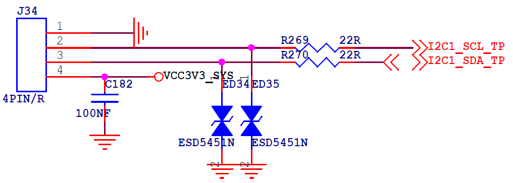
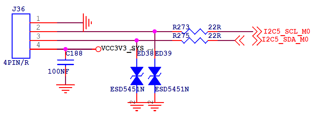
YY3568 has two extended I2C interfaces. The interfaces are shown as follows. You can see the pin screen on the backplane for details.

¶ I2C protocol timing details
¶ Start/stop signal
-
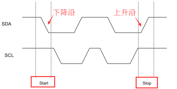
Starting signal: From the previous introduction, we can know that the I2C bus is idle, SCL and SDA are in a high state. During the time the clock line SCL remains high, the jump in the data line SDA from ** high ** to ** low ** is called the start signal of I2C.
-
Stop signal: During the time that the clock line SCL remains high, the jump in the data line SDA from ** low ** to ** high ** is called the stop signal of I2C.
¶ Transmission of data bits
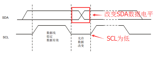
- Data bit transmission: After the initial signal occurs, an I2C communication begins. At this time **SCL stabilizes at a low level **, the SDA is allowed to jump, and then samples this bit of data when SCL is at a rising edge. Here is more verbose for the reader to understand, just described the start and stop signals, **SCL is the SDA to complete the level jump during the high level **. Pay attention to the comparison here to give you a better understanding of how the I2C bus cleverly distinguishes between whether you are transferring data or controlling start and stop.
¶ Answer bit information
-
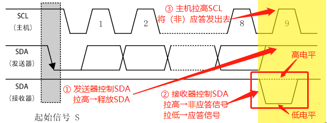
Answer bit information: After the 8-bit data transmission is finished, the sending end ** pulls up the SDA to release the control of the SDA. At this time, the receiving end ** * obtains the control of the SDA. If it is pulled down, it means that an answer signal (ACK) has been sent, if it is pulled up, it means that a non-answer signal (NACK) has been sent, and then the host pulls up the SCL and sends this signal back to the ** sending end **
-
Answer signal (ACK): After the 8-bit data is sent, the receiver pulls down the SDA to send an answer signal. It can be used to indicate that a byte of data is successfully received, or it can be used when the host is the receiving end (** the host ** reads ** operation), and the sender can continue to send data before receiving the last byte.
-
Non-answer signal (NACK): After the 8-bit data is sent, the receiver does not operate on the SDA, which represents a non-answer signal. It can be used to indicate that a byte of data has not been successfully transmitted, or when the host is the receiving end (** the host ** reads ** operation), after it receives the last byte, the host (receiver) should send a NACK signal to notify the slave (sender) to end the data transmission and release the data bus. So that the host (receiver) sends a stop signal to stop the communication.
¶ Determination of read/write on the host side
Before we establish communication between the host and slave, we first need to determine two points.
-
- How does the host distinguish who to communicate with
-
- How does the host distinguish between read and write
The first question, as we said when we introduced the I2C protocol, we can distinguish different slave devices by their addresses. So from the device address we can distinguish the objects we need to communicate with.
Second, we can determine whether to read or write by the flag bit. If you set 0, you write, and if you set 1, you read
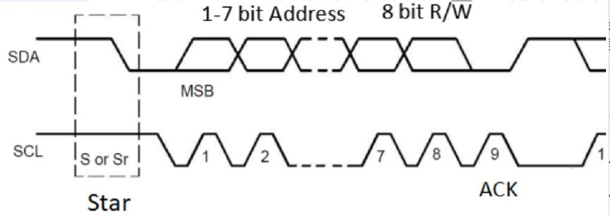
In summary, after the initial signal is initiated, I2C communication will first send 7 bits of address and 1 bit of read and write flag bit, a total of 8 bits of data (the transmission process is consistent with the data transmission mentioned before, so we will not repeat it here). It is used to determine the object of communication and the direction of data.
¶ Complete communication process
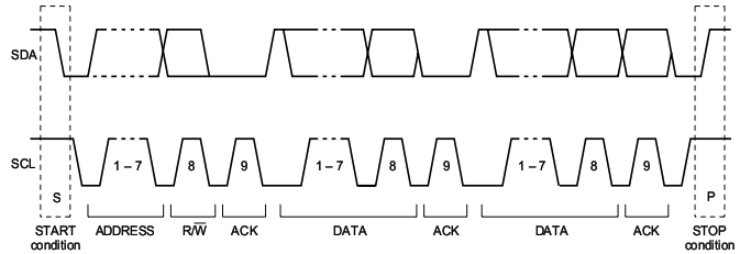
The picture above is the complete communication flow of I2C. Combined with the above content, I believe you will easily understand this picture. To briefly introduce the above process, the initial signal is initiated, and then the address is sent, and the slave machine is answered, and then the 8-bit data is sent, and the slave machine is answered, and then the 8-bit data is sent, and the slave machine is answered. Finally, the end signal is initiated and the communication ends.
¶ Waveform instance
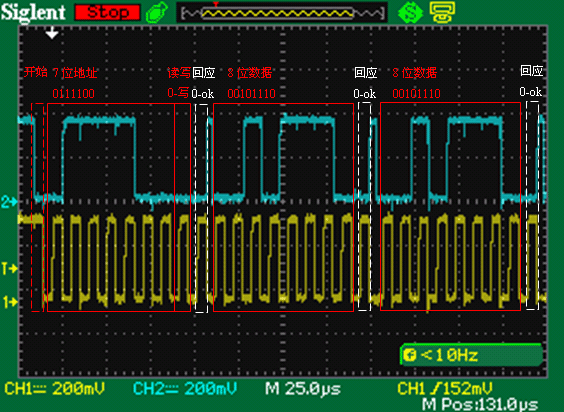
It can be seen from the figure that the timing is as follows:
-
- Initiated by the host, when the SCL is high power level, the SDA is from high to low shear, forming a start signal;
- This is followed by a 7-bit address and a read/write flag, where the 7-bit address is 0111100, or 0x3c.
-
- Then on the next clock, the host releases the SDA at a high level, at which time the slave responds and pulls the SDA down.
-
- Followed by two 8-bit data 00101110 and ACK, i.e. 0x2E.
¶ Use and compilation of I2C-TOOLS
¶ Obtain the I2C tool
I2C_TOOLS download link: https://mirrors.edge.kernel.org/pub/software/utils/i2c-tools/
What the author downloaded here is version i2c-tools-4.3
¶ Add source code to android
After downloading, unzip the package to the tinkerR-Android9/external directory (this is the Android system code, you can refer to the environment building chapter to obtain the download method)
-
- Create the Android.mk file in the i2c-tools-3.1.1 folder
-
- Edit the Android.mk file as follows
LOCAL_PATH:= $(call my-dir)

include $(CLEAR_VARS)

LOCAL_MODULE_TAGS := optional
LOCAL_C_INCLUDES += $(LOCAL_PATH)/include $(LOCAL_PATH) $(LOCAL_PATH)/$(KERNEL_DIR)/include
LOCAL_SRC_FILES := tools/i2cbusses.c tools/util.c
LOCAL_MODULE := i2c-tools
include $(BUILD_STATIC_LIBRARY)

include $(CLEAR_VARS)

LOCAL_MODULE_TAGS := optional
LOCAL_SRC_FILES:=tools/i2cdetect.c
LOCAL_MODULE:=i2cdetect
LOCAL_CPPFLAGS += -DANDROID
LOCAL_SHARED_LIBRARIES:=libc
LOCAL_STATIC_LIBRARIES := i2c-tools
LOCAL_C_INCLUDES += $(LOCAL_PATH)/include $(LOCAL_PATH) $(LOCAL_PATH)/$(KERNEL_DIR)/include
include $(BUILD_EXECUTABLE)

include $(CLEAR_VARS)

LOCAL_MODULE_TAGS := optional
LOCAL_SRC_FILES:=tools/i2cget.c
LOCAL_MODULE:=i2cget
LOCAL_CPPFLAGS += -DANDROID
LOCAL_SHARED_LIBRARIES:=libc
LOCAL_STATIC_LIBRARIES := i2c-tools
LOCAL_C_INCLUDES += $(LOCAL_PATH)/include $(LOCAL_PATH) $(LOCAL_PATH)/$(KERNEL_DIR)/include
include $(BUILD_EXECUTABLE)

include $(CLEAR_VARS)

LOCAL_MODULE_TAGS := optional
LOCAL_SRC_FILES:=tools/i2cset.c
LOCAL_MODULE:=i2cset
LOCAL_CPPFLAGS += -DANDROID
LOCAL_SHARED_LIBRARIES:=libc
LOCAL_STATIC_LIBRARIES := i2c-tools
LOCAL_C_INCLUDES += $(LOCAL_PATH)/include $(LOCAL_PATH) $(LOCAL_PATH)/$(KERNEL_DIR)/include
include $(BUILD_EXECUTABLE)

include $(CLEAR_VARS)

LOCAL_MODULE_TAGS := optional
LOCAL_SRC_FILES:=tools/i2cdump.c
LOCAL_MODULE:=i2cdump
LOCAL_CPPFLAGS += -DANDROID
LOCAL_SHARED_LIBRARIES:=libc
LOCAL_STATIC_LIBRARIES := i2c-tools
LOCAL_C_INCLUDES += $(LOCAL_PATH)/include $(LOCAL_PATH) $(LOCAL_PATH)/$(KERNEL_DIR)/include
include $(BUILD_EXECUTABLE)
-
- Create the Android.mk file in the i2c-tools-4.3 folder
- 2.Edit the Android.mk file as follows
LOCAL_PATH:= $(call my-dir)

################### i2c-tools #########################
include $(CLEAR_VARS)

LOCAL_MODULE_TAGS := eng
LOCAL_MODULE := i2c-tools

LOCAL_SRC_FILES := \
    tools/i2cbusses.c \
    tools/util.c \
    lib/smbus.c

LOCAL_C_INCLUDES += \
    $(LOCAL_PATH) \
    $(LOCAL_PATH)/include

#LOCAL_CFLAGS := -g -Wall -Werror -Wno-unused-parameter
include $(BUILD_STATIC_LIBRARY)

################### i2cdetect #########################
include $(CLEAR_VARS)

LOCAL_MODULE_TAGS := eng
LOCAL_MODULE:=i2cdetect

LOCAL_SRC_FILES:= \
    tools/i2cdetect.c

LOCAL_C_INCLUDES += \
    $(LOCAL_PATH) \
    $(LOCAL_PATH)/include

LOCAL_SHARED_LIBRARIES:= \
    libc
LOCAL_STATIC_LIBRARIES := \
    i2c-tools

LOCAL_CPPFLAGS += -DANDROID

include $(BUILD_EXECUTABLE)

#################### i2cget ###########################
include $(CLEAR_VARS)

LOCAL_MODULE_TAGS := eng
LOCAL_MODULE:=i2cget

LOCAL_SRC_FILES:= \
    tools/i2cget.c

LOCAL_C_INCLUDES += \
    $(LOCAL_PATH) \
    $(LOCAL_PATH)/include

LOCAL_SHARED_LIBRARIES:= \
    libc
LOCAL_STATIC_LIBRARIES := \
    i2c-tools

LOCAL_CPPFLAGS += -DANDROID

include $(BUILD_EXECUTABLE)

##################### i2cset ##########################
include $(CLEAR_VARS)

LOCAL_MODULE_TAGS := eng
LOCAL_MODULE:=i2cset

LOCAL_SRC_FILES:= \
    tools/i2cset.c

LOCAL_C_INCLUDES += \
    $(LOCAL_PATH) \
    $(LOCAL_PATH)/include

LOCAL_SHARED_LIBRARIES:= \
    libc
LOCAL_STATIC_LIBRARIES := \
    i2c-tools

LOCAL_CPPFLAGS += -DANDROID

include $(BUILD_EXECUTABLE)

##################### i2cdump #########################
include $(CLEAR_VARS)

LOCAL_MODULE_TAGS := eng
LOCAL_MODULE:=i2cdump

LOCAL_SRC_FILES:= \
    tools/i2cdump.c

LOCAL_C_INCLUDES += \
    $(LOCAL_PATH) \
    $(LOCAL_PATH)/include

LOCAL_SHARED_LIBRARIES:= \
    libc
LOCAL_STATIC_LIBRARIES := \
    i2c-tools

LOCAL_CPPFLAGS += -DANDROID

include $(BUILD_EXECUTABLE)

################### i2ctransfer #######################
include $(CLEAR_VARS)

LOCAL_MODULE_TAGS := eng
LOCAL_MODULE:=i2ctransfer

LOCAL_SRC_FILES:= \
    tools/i2ctransfer.c

LOCAL_C_INCLUDES += \
    $(LOCAL_PATH) \
    $(LOCAL_PATH)/include

LOCAL_SHARED_LIBRARIES:= \
    libc
LOCAL_STATIC_LIBRARIES := \
    i2c-tools

LOCAL_CPPFLAGS += -DANDROID

include $(BUILD_EXECUTABLE)
¶ compile module
-
- First of all, you need to confirm that the android system source code has been successfully compiled
-
- Run the following command in the root directory of the android operating system
./docker_builder/docker-builder-run.sh	//Enter the docker environment
source build/envsetup.sh								//Configuring environment variables
lunch xxx							//xxx refers to the board-level configuration of the target board
- 3.Go to the i2c_tools directory and start compiling
cd external/i2c-tools-4.3/
mm																			// Android source code single compilation command
- 4.After the success of the compilation, can be in the out/target/product/XXX/system/bin directory to generate five executable file, as follows:
i2cdetect i2cdump i2cget i2cset i2ctransfer//This parameter is available only in version 4.x or later
- 5.Use the adb tool to push the file to the /system/bin directory of the android device (to change the executable permissions by using the chmod command), so that the device comes with these commands. Of course, it is also possible to reorganize the system and then download the image as a whole to make the device with these command functions, but this is more troublesome.
¶ tool use
- 1.Use i2cdetect to detect how many i2c buses are on the system
YY3568:/ # i2cdetect -l


i2c-1   i2c             rk3x-i2c                                I2C Adapter
i2c-6   i2c             DP-AUX                                  I2C Adapter
i2c-4   i2c             rk3x-i2c                                I2C Adapter
i2c-0   i2c             rk3x-i2c                                I2C Adapter
i2c-7   i2c             DesignWare HDMI                         I2C Adapter
i2c-5   i2c             rk3x-i2c                                I2C Adapter
- 2.Use i2cdetect to detect devices attached to the i2c bus
YY3568:/ # i2cdetect -y 5								//Here, 5 indicates the bus device number, that is, i2c-5 is detected
     0  1  2  3  4  5  6  7  8  9  a  b  c  d  e  f
00:                         -- -- -- -- -- -- -- --
10: -- -- -- -- -- -- -- -- -- -- -- -- -- -- -- --
20: -- -- -- -- -- -- -- -- -- -- -- -- -- -- -- --
30: -- -- -- -- -- -- -- -- -- -- -- -- -- -- -- --
40: -- -- -- -- -- -- -- -- -- -- -- -- -- -- -- --
50: 50 51 52 53 -- -- -- -- -- -- -- -- -- -- -- --		//The addresses of the mounted devices are 0x50 0x51 0x52 0x53
60: -- -- -- -- -- -- -- -- -- -- -- -- -- -- -- --
70: -- -- -- -- -- -- -- --
- 3.Use i2cdump to view the values of all the device registers
YY3568:/ # i2cdump -f -y 5 0x50				//Detects the slave device with address 0x50 on the i2c-5 bus
No size specified (using byte-data access)
     0  1  2  3  4  5  6  7  8  9  a  b  c  d  e  f    0123456789abcdef
00: 50 eb f6 3f f9 83 32 31 31 30 39 33 33 39 38 32    P?????2110933982
10: 30 30 31 30 31 00 00 00 00 00 ff ff ff ff ff ff    00101...........
20: ff ff ff ff ff ff ff ff ff ff ff ff ff ff ff ff    ................
30: ff ff ff ff ff ff ff ff ff ff ff ff ff ff ff ff    ................
40: ff ff ff ff ff ff ff ff ff ff ff ff ff ff ff ff    ................
50: ff ff ff ff ff ff ff ff ff ff ff ff ff ff ff ff    ................
60: ff ff ff ff ff ff ff ff ff ff ff ff ff ff ff ff    ................
70: ff ff ff ff ff ff ff ff ff ff ff ff ff ff ff ff    ................
80: ff ff ff ff ff ff ff ff ff ff ff ff ff ff ff ff    ................
90: ff ff ff ff ff ff ff ff ff ff ff ff ff ff ff ff    ................
a0: ff ff ff ff ff ff ff ff ff ff ff ff ff ff ff ff    ................
b0: ff ff ff ff ff ff ff ff ff ff ff ff ff ff ff ff    ................
c0: ff ff ff ff ff ff ff ff ff ff ff ff ff ff ff ff    ................
d0: ff ff ff ff ff ff ff ff ff ff ff ff ff ff ff ff    ................
e0: ff ff ff ff ff ff ff ff ff ff ff ff ff ff ff ff    ................
f0: ff ff ff ff ff ff ff ff ff ff ff ff ff ff ff ff    ................
- 4.Use i2cset to set the value of a single register
YY3568:/ # i2cdump -f -y 5 0x30 0xFC 0x3F //Write 0x3F to device register address 0xFC at address 0x30 on the i2c-5 bus
- 5.Use i2cget to get the value of a single register
YY3568:/ # i2cget -f -y 5 0x50 0x01						//Gets the value of the 0x01 register to the device at address 0x50 on the i2c-5 bus
0xeb
-
- Use i2ctransfer,i2ctransfer supports 16bit and 32bit register read and write, while i2cset and i2cget only support 8bit register
// Write 0xFA to register 0x3288 of 0x30 device on i2c-1
YY3568:/ # i2ctransfer -f -y 5 w3@0x30 0x32 0x88 0xFA

// Read 2 bytes of data to the 0x30 device 0x3288 register on i2c-1
YY3568:/ # i2ctransfer -f -y 5 w2@0x30 0x32 0x88 r2
// 1. i2cdetect to detect how many i2c buses are on the syst
YY3568:/ # i2cdetect -l
i2c-1   i2c             rk3x-i2c                                I2C Adapter
i2c-6   i2c             DP-AUX                                  I2C Adapter
i2c-4   i2c             rk3x-i2c                                I2C Adapter
i2c-0   i2c             rk3x-i2c                                I2C Adapter
i2c-7   i2c             DesignWare HDMI                         I2C Adapter
i2c-5   i2c             rk3x-i2c                                I2C Adapter

// 2.i2cdetect to detect how many i2c buses are on the syst
YY3568:/ # i2cdetect -y  5								//此处5代表总线设备号 即检测的是i2c-5
     0  1  2  3  4  5  6  7  8  9  a  b  c  d  e  f
00:          -- -- -- -- -- -- -- -- -- -- -- -- --
10: -- -- -- -- -- -- -- -- -- -- -- -- -- -- -- --
20: -- -- -- -- -- -- -- -- -- -- -- -- -- -- -- --
30: 30 31 32 -- -- -- -- -- -- -- -- -- -- -- -- --
40: -- -- -- -- -- -- -- -- -- -- -- -- -- -- -- --
50: -- -- -- -- -- -- -- -- -- -- -- -- -- -- -- --
60: -- -- -- -- -- -- -- -- -- -- -- -- -- -- -- --
70: -- -- -- -- -- -- -- --


// 3.用i2cdump查看器件所有寄存器的值
YY3568:/ # i2cdump -f -y 5 0x31			//检测i2c-5总线上地址为0x30的从设备
    0  1  2  3  4  5  6  7  8  9  a  b  c  d  e  f    0123456789abcdef
00: 6c 6c 6c 6c 6c 6c 6c 6c 6c 6c 6c 6c 6c 6c 6c 6c    llllllllllllllll
10: 6c 6c 6c 6c 6c 6c 6c 6c 6c 6c 6c 6c 6c 6c 6c 6c    llllllllllllllll
20: 6c 6c 6c 6c 6c 6c 6c 6c 6c 6c 6c 6c 6c 6c 6c 6c    llllllllllllllll
30: 6c 6c 6c 6c 6c 6c 6c 6c 6c 6c 6c 6c 6c 6c 6c 6c    llllllllllllllll
40: 6c 6c 6c 6c 6c 6c 6c 6c 6c 6c 6c 6c 6c 6c 6c 6c    llllllllllllllll
50: 6c 6c 6c 6c 6c 6c 6c 6c 6c 6c 6c 6c 6c 6c 6c 6c    llllllllllllllll
60: 6c 6c 6c 6c 6c 6c 6c 6c 6c 6c 6c 6c 6c 6c 6c 6c    llllllllllllllll
70: 6c 6c 6c 6c 6c 6c 6c 6c 6c 6c 6c 6c 6c 6c 6c 6c    llllllllllllllll
80: 6c 6c 6c 6c 6c 6c 6c 6c 6c 6c 6c 6c 6c 6c 6c 6c    llllllllllllllll
90: 6c 6c 6c 6c 6c 6c 6c 6c 6c 6c 6c 6c 6c 6c 6c 6c    llllllllllllllll
a0: 6c 6c 6c 6c 6c 6c 6c 6c 6c 6c 6c 6c 6c 6c 6c 6c    llllllllllllllll
b0: 6c 6c 6c 6c 6c 6c 6c 6c 6c 6c 6c 6c 6c 6c 6c 6c    llllllllllllllll
c0: 6c 6c 6c 6c 6c 6c 6c 6c 6c 6c 6c 6c 6c 6c 6c 6c    llllllllllllllll
d0: 6c 6c 6c 6c 6c 6c 6c 6c 6c 6c 6c 6c 6c 6c 6c 6c    llllllllllllllll
e0: 6c 6c 6c 6c 6c 6c 6c 6c 6c 6c 6c 6c 6c 6c 6c 6c    llllllllllllllll
f0: 6c 6c 6c 6c 6c 6c 6c 6c 6c 6c 6c 6c 6c 6c 6c 6c    llllllllllllllll

//4.用i2cset来设置单个寄存器的值
YY3568:/ # i2cdump -f -y 5 0x31 0xFC 0x3F				//往i2c-5总线上地址为0x30的设备寄存器地址0xFC上写入0x3F


//5.用i2cget来获取单个寄存器的值

YY3568:/ # i2cget -f -y 5 0x31 0xFC						//往i2c-5总线上地址为0x31的设备获取0xFC寄存器的值
0x3ff


//6.i2ctransfer使用,i2ctransfer支持16bit和32bit寄存器的读写,而i2cset和i2cget只支持8bit的寄存器

//往i2c-5上0x32器件 0x3288寄存器 写入0xFA
YY3568:/ # i2ctransfer -f -y 5 w3@0x32 0x32 0x88 0xFA

//往i2c-5上0x32器件 0x3288寄存器 读取2个字节数据
YY3568:/ # i2ctransfer -f -y 5 w2@0x32 0x32 0x88 r2
¶ C语言调用I2C
#include <stdio.h>
#include <string.h>
#include <sys/ioctl.h>
#include <unistd.h>
#include <fcntl.h>
#include <linux/i2c-dev.h>
#include <linux/i2c.h>
/* slave device所对应的I2C控制器的设备节点 */
#define I2C_DEVICE "/dev/i2c-5"
/* slave_device的I2C设备地址 */
#define SLAVE_DEVICE_ADDR 0x32
/*函数名:slave_device_write
**功能:向slave device写数据
**参数:fd:slave device对应I2C控制器设备节点的文件名
** dev_addr:slave device的I2C从设备地址
** reg_addr:slave device的寄存器地址
** data_buf:要向slave device写数据的数据buf
** len:要写多少个字节。本例中当前最大支持为8个字节
**返回值:负数表示操作失败,其他为成功
*/
int slave_device_write(int fd, unsigned char dev_addr, unsigned char reg_addr, unsigned char * data_buf,int len)
{
int ret;
unsigned char msg_buf[9];
struct i2c_rdwr_ioctl_data data;
struct i2c_msg messages;
/* 1. 构建msg_buf*/
/* 1.1. 将要操作的寄存器首地址赋给要进行I2C数据通信的首字节数据 */
msg_buf[0] = reg_addr;
/* 1.2. 将要向slave_device写数据的数据buf赋在I2C数据通信中slave device寄存器的后面 */
if (len < 9) { /* 本demo最大支持一次向slave device写一页大小的8个字节数据 */
memcpy((void *) &msg_buf[1], data_buf, len); //第1位之后是数据
} else {
printf("This function supports up to 8 bytes at a time !!!\n");
return -1;
}
/* 2. 构建 struct i2c_msg messages */
/* 2.1. 赋值slave device的I2C从设备地址 */
messages.addr = dev_addr;
/* 2.2. 赋值flags为本次I2C通信完成写功能 */
messages.flags = 0;
/* 2.3. 赋值len为数据buf的长度 + slave device寄存器地址的数据长度 */
messages.len = len+1;
/* 2.4. 构建消息包的数据buf*/
messages.buf = msg_buf;
/* 3. 构建struct i2c_rdwr_ioctl_data data */
/* 3.1. 将准备好的消息包赋值给i2c_rdwr_ioctl_data中的msgs消息*/
data.msgs = &messages;
/* 3.2. 由于本次I2C通信只有写动作,所以消息数为1次 */
data.nmsgs = 1;
/* 4. 调用驱动层的读写组合的I2C数据传输 */
if(ioctl(fd, I2C_RDWR, &data) < 0)
{
printf("I2C_RDWR err \n");
return -1;
}
/* 5. 等待I2C总线写入完成 */
sleep(1);
return 0;
}
/*函数名:slave_device_read
**功能:从slave_device读数据
**参数:fd:slave_device对应I2C控制器设备节点的文件名
** dev_addr:slave_device的I2C从设备地址
** reg_addr:slave_device的寄存器地址
** data_buf:存放从slave_device读数据的buf
** len:要读多少个字节。
**返回值:负数表示操作失败,其他为成功
*/
int slave_device_read(int fd, unsigned char dev_addr, unsigned char reg_addr, unsigned char * data_buf,int len)
{
int ret;
unsigned char msg_buf[9];
struct i2c_rdwr_ioctl_data data;
struct i2c_msg messages[2];
/* 1. 构建 struct i2c_msg messages */
/* 1.1. 构建第一条消息 messages[0] */
/* 1.1.1. 赋值slave_device的I2C从设备地址 */
messages[0].addr = dev_addr;
/* 1.1.2. 赋值flags为本次I2C通信完成写动作 */
messages[0].flags = 0;
/* 1.1.3. 赋值len为slave_device寄存器地址的数据长度是1 */
messages[0].len = 1;
/* 1.1.4. 本次写动作的数据是要读取slave_device的寄存器首地址*/
messages[0].buf = ®_addr;
/* 1.2. 构建第二条消息 messages[1] */
/* 1.2.1. 赋值slave_device的I2C从设备地址 */
messages[1].addr = dev_addr;
/* 1.1.2. 赋值flags为本次I2C通信完成读动作 */
messages[1].flags = I2C_M_RD;
/* 1.1.3. 赋值len为要读取slave_device寄存器数据长度len */
messages[1].len = len;
/* 1.1.4. 本次读动作的数据要存放的buf位置*/
messages[1].buf = data_buf;
/* 2. 构建struct i2c_rdwr_ioctl_data data */
/* 2.1. 将准备好的消息包赋值给i2c_rdwr_ioctl_data中的msgs消息*/
data.msgs = messages;
/* 2.2. 由于本次I2C通信既有写动作也有读动作,所以消息数为2次 */
data.nmsgs = 2;
/* 3. 调用驱动层的读写组合的I2C数据传输 */
if(ioctl(fd, I2C_RDWR, &data) < 0)
{
printf("I2C_RDWR err \n");
return -1;
}
/* 4. 等待I2C总线读取完成 */
sleep(1);
return 0;
}
int main()
{
int fd,i,ret=0;
unsigned char w_add=0x10;
/* 将要读取的数据buf*/
unsigned char rd_buf[8] = {0};
/* 要写的数据buf*/
unsigned char wr_buf[8] = {0};
printf("hello,this is I2C_RDWR i2c test \n");
/* 打开slave_device对应的I2C控制器文件 */
fd =open(I2C_DEVICE, O_RDWR);
if (fd< 0)
{
printf("open"I2C_DEVICE"failed \n");
}
/* 把要写入的数据写入到后面的buf中 */
for(i=0;i<8;i++)
wr_buf[i]=i;
/* 通过I2C_RDWR完成向slave_device读数据的功能 */
slave_device_write(fd,SLAVE_DEVICE_ADDR,w_add,wr_buf,8);
/* 通过I2C_RDWR完成向slave_device写数据的功能 */
slave_device_read(fd,SLAVE_DEVICE_ADDR,w_add,rd_buf,8);
for(i=0;i<8;i++)
{
printf("rd_buf is :%d\n",rd_buf[i]);
}
/* 完成操作后,关闭slave_device对应的I2C控制器的设备文件 */
close(fd);
return 0;
}
¶ JAVA调用I2C
1.JAVA调用I2C的工程创建与GPIO类似,请读者自行创建,其工程目录下图。注意在创建包名的时候,请使用com.bin.i2ctest,因为下文的附件是按这个包名来构建的,所以读者应保持与该包名一致。

2.所需文件名在图示中所包含(CMakeLists.txt、MainActivity、activity_main.xml创建工程后存在,用附件对应同名文件覆盖即可;test_gpio.c放到cpp文件目录下)。
i2c附件.zip
¶ UART调用实例
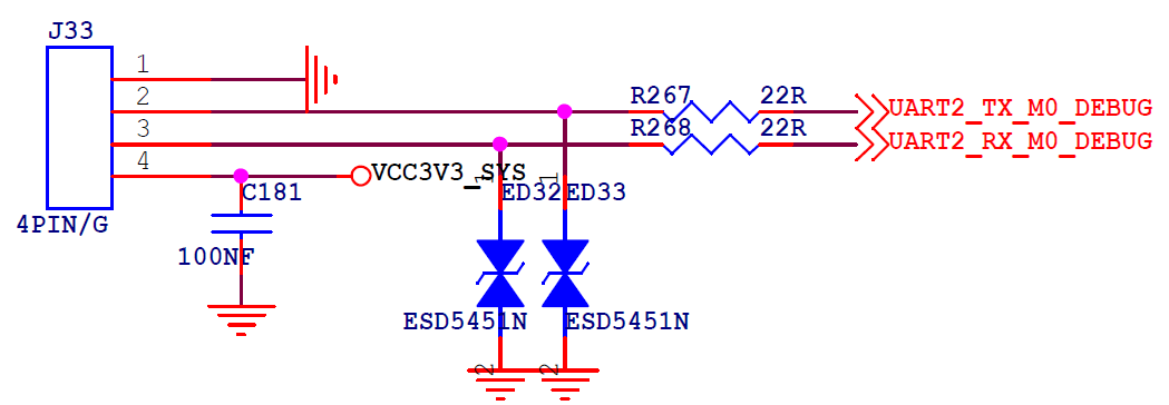
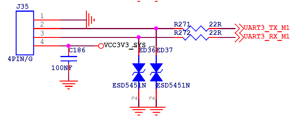
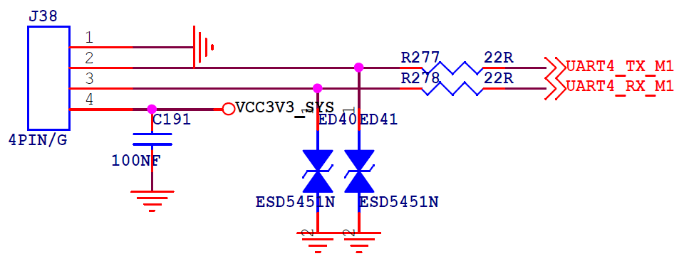
YY3568支持五路UART,其中UART2作为DEBUG,其他四个作为普通串口使用。对应的串口引脚如下所示

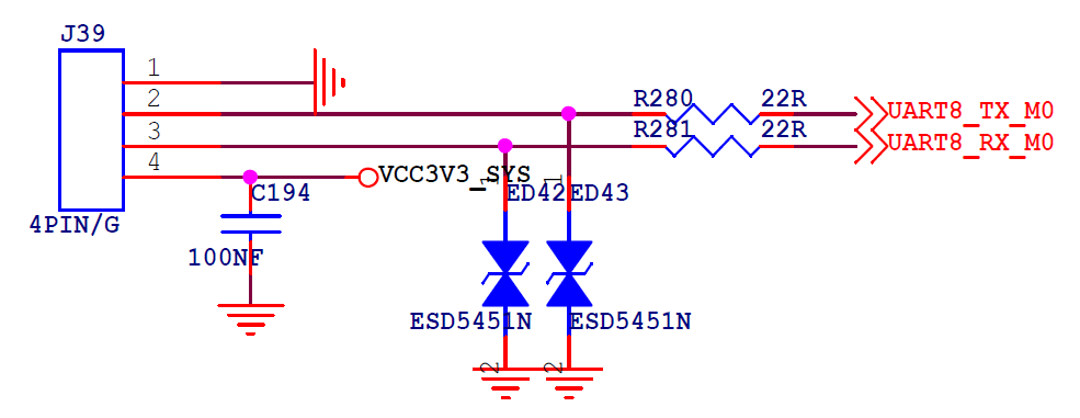
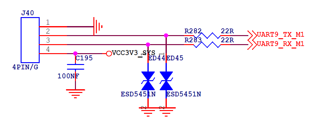
¶ shell调用UART
//查看串口信息
YY3568:/ # stty -F /dev/ttyS4
speed 9600 baud; line = 0;
hupcl clocal
-brkint ixon -imaxbel

//设置串口波特率为115200
YY3568:/ # stty -F /dev/ttyS4 speed 115200
9600
YY3568:/ # stty -F /dev/ttyS4
speed 115200 baud; line = 0;
hupcl clocal
-brkint ixon -imaxbel

//发送数据
YY3568:/ # echo "Message From YY3568" > /dev/ttyS4

//接收数据
YY3568:/ # cat /dev/ttyS4
Message From My PC
¶ C语言调用UART
#include <sys/types.h>
#include <sys/stat.h>
#include <fcntl.h>
#include <termios.h>
#include <stdio.h>
#include <unistd.h>

int speed_arr[] = { B115200, B38400, B19200, B9600, B4800, B2400, B1200, B300,
          B38400, B19200, B9600, B4800, B2400, B1200, B300, };
int name_arr[] = {115200, 38400,  19200,  9600,  4800,  2400,  1200,  300, 38400,
          19200,  9600, 4800, 2400, 1200,  300, };

void set_speed(int fd, int speed){
  int   i;
  int   status;
  struct termios   Opt;
  tcgetattr(fd, &Opt);
  for ( i= 0;  i < sizeof(speed_arr) / sizeof(int);  i++) {
    if  (speed == name_arr[i]) {
      tcflush(fd, TCIOFLUSH);
      cfsetispeed(&Opt, speed_arr[i]);
      cfsetospeed(&Opt, speed_arr[i]);
      status = tcsetattr(fd, TCSANOW, &Opt);
      if  (status != 0) {
        perror("tcsetattr fd1");
        return;
      }
      tcflush(fd,TCIOFLUSH);
    }
  }
}


/**
*@brief   设置串口数据位,停止位和效验位
*@param  fd     类型  int  打开的串口文件句柄
*@param  databits 类型  int 数据位   取值 为 7 或者8
*@param  stopbits 类型  int 停止位   取值为 1 或者2
*@param  parity  类型  int  效验类型 取值为N,E,O,,S
*/
int set_Parity(int fd,int databits,int stopbits,int parity)
{
    struct termios options;
    if  ( tcgetattr( fd,&options)  !=  0) {
        perror("SetupSerial ");
              printf("setup serial failurer\n");
        return(-1);
    }
    options.c_cflag &= ~CSIZE;
    switch (databits) /*设置数据位数*/
    {
    case 7:
        options.c_cflag |= CS7;
        break;
    case 8:
        options.c_cflag |= CS8;
        break;
    default:
        fprintf(stderr,"Unsupported data size\n");
            return (-1);
    }

    switch (parity)
    {
    case 'n':
    case 'N':
        options.c_cflag &= ~PARENB;   /* Clear parity enable */
        options.c_iflag &= ~INPCK;     /* Enable parity checking */
        break;
    case 'o':
    case 'O':
        options.c_cflag |= (PARODD | PARENB); /* 设置为奇效验*/
        options.c_iflag |= INPCK;             /* Disnable parity checking */
        break;
    case 'e':
    case 'E':
        options.c_cflag |= PARENB;     /* Enable parity */
        options.c_cflag &= ~PARODD;   /* 转换为偶效验*/
        options.c_iflag |= INPCK;       /* Disnable parity checking */
        break;
    case 'S':
    case 's':  /*as no parity*/
        options.c_cflag &= ~PARENB;
        options.c_cflag &= ~CSTOPB;
        break;
    default:
        fprintf(stderr,"Unsupported parity\n");
        return (-1);
    }
    /* 设置停止位*/
    switch (stopbits)
    {
    case 1:
        options.c_cflag &= ~CSTOPB;
        break;
    case 2:
        options.c_cflag |= CSTOPB;
       break;
    default:
         fprintf(stderr,"Unsupported stop bits\n");
         return (-1);
    }
    /* Set input parity option */
    if (parity != 'n' && parity != 'N')
    	options.c_iflag |= INPCK;
    tcflush(fd,TCIFLUSH);
    options.c_cc[VTIME] = 150; /* 设置超时15 seconds*/
    options.c_cc[VMIN] = 0; /* Update the options and do it NOW */

    options.c_lflag  &= ~(ICANON | ECHO | ECHOE | ISIG);  /*Input*/
    options.c_oflag  &= ~(OPOST|ONLCR|OCRNL);   /*Output*/
    options.c_iflag &= ~(BRKINT | ICRNL | INPCK | ISTRIP | IXON | INLCR|IGNCR);
    if (tcsetattr(fd,TCSANOW,&options) != 0)
    {
    	perror("SetupSerial 3");
    	return (-1);
    }
    return (0);
}


int set_serial_port(int fd, speed_t speed, int databits,int stopbits,int parity)
{
    int ret;
   set_speed(fd, speed);
   ret = set_Parity(fd, databits, stopbits, parity);

   return ret;

}


int open_serial_port(char *dev_path)
{
    int fd;
    if (dev_path == NULL)
        return -1;
    fd=open(dev_path,O_RDWR | O_NOCTTY);
    if(fd==-1)
    {
        printf("open serialport failed [%s]\n", dev_path);
        perror("open serialport failed\n");
        return(-1);
    }
    fcntl(fd, F_SETFL, 0);

    return fd;

}

int init_uart(char * device_name, speed_t speed, int databits,int stopbits,int parity)
{
    int ret;
    int uart_fd = 0;
    uart_fd = open_serial_port(device_name);
    if(uart_fd<0)
    {
        printf("open  serial port failed\n");
        return -1;
    }

    ret=set_serial_port(uart_fd, speed, databits, stopbits, parity);
    if(ret==-1)
    {
        printf("set  serial port failed\n");
        return -1;
    }
    return uart_fd;


}

int close_uart(int uart_fd)
{
    if (uart_fd > 0)
        close(uart_fd);

    return 0;
}

int main()
{

     int gblUartFd = -1;
     int ret;
     unsigned char buf[5]={0,};
     gblUartFd = init_uart("/dev/ttyS4", 115200, 8, 1, 'N');
     while(1)
     {
     	ret = read(gblUartFd , buf, sizeof(char)*5);
     	printf("buf=%s",buf);
     	sleep(1);
     }
     close_uart(gblUartFd);
     return 0;
}
¶ Java调用UART
在上方的创建
系统app demo的基础上添加如下代码。
- 在
activity_main.xml文件修改为如下代码。
<LinearLayout xmlns:android="http://schemas.android.com/apk/res/android"
    android:layout_width="match_parent"
    android:layout_height="match_parent"
    android:orientation="vertical"
    >
    <ScrollView android:id="@+id/scroll"
        android:layout_width="match_parent"
        android:layout_height="0px"
        android:layout_weight="1"
        >
        <TextView android:id="@+id/log"
            android:layout_width="match_parent"
            android:layout_height="wrap_content"
            android:layout_marginTop="25dp"
            android:textSize="12sp"
            android:textColor="#000000"
            />
    </ScrollView>

    <EditText android:id="@+id/message"
        android:layout_width="match_parent"
        android:layout_height="wrap_content"
        android:singleLine="true" />
</LinearLayout>
- 在
MainActivity.java文件修改为如下内容。
package com.youyeetoo.demo;

import androidx.appcompat.app.AppCompatActivity;

import android.annotation.SuppressLint;
import android.os.Bundle;
import android.hardware.SerialManager;
import android.hardware.SerialPort;
import android.os.Handler;
import android.os.Message;
import android.util.Log;
import android.view.KeyEvent;
import android.widget.EditText;
import android.widget.TextView;

import java.io.IOException;
import java.nio.ByteBuffer;
public class MainActivity extends AppCompatActivity implements Runnable, TextView.OnEditorActionListener {

    private static final String TAG = "SerialChat";
    private TextView mLog;
    private EditText mEditText;
    private ByteBuffer mInputBuffer;
    private ByteBuffer mOutputBuffer;
    private SerialManager mSerialManager;
    private SerialPort mSerialPort;
    private boolean mPermissionRequestPending;

    private static final int MESSAGE_LOG = 1;

    @SuppressLint({"WrongConstant", "MissingInflatedId"})
    @Override
    protected void onCreate(Bundle savedInstanceState) {
        super.onCreate(savedInstanceState);
        setContentView(R.layout.activity_main);

        mSerialManager = (SerialManager)getSystemService("serial");

        mLog = (TextView)findViewById(R.id.log);
        mEditText = (EditText)findViewById(R.id.message);
        mEditText.setOnEditorActionListener(this);

        if (false) {
            mInputBuffer = ByteBuffer.allocateDirect(1024);
            mOutputBuffer = ByteBuffer.allocateDirect(1024);
        } else {
            mInputBuffer = ByteBuffer.allocate(1024);
            mOutputBuffer = ByteBuffer.allocate(1024);
        }
    }

    @Override
    public void onResume() {
        super.onResume();

        String[] ports = mSerialManager.getSerialPorts();
        if (ports != null && ports.length > 0) {
            try {
                mSerialPort = mSerialManager.openSerialPort(ports[0], 115200);
                if (mSerialPort != null) {
                    new Thread(this).start();
                }
            } catch (IOException e) {
            }
        }

    }

    @Override
    public void onPause() {
        super.onPause();

    }

    @Override
    public void onDestroy() {
        if (mSerialPort != null) {
            try {
                mSerialPort.close();
            } catch (IOException e) {
            }
            mSerialPort = null;
        }
        super.onDestroy();
    }

    @Override
    public boolean onEditorAction(TextView v, int actionId, KeyEvent event) {
        if (/* actionId == EditorInfo.IME_ACTION_DONE && */ mSerialPort != null) {
            try {
                String text = v.getText().toString();
                Log.d(TAG, "write: " + text);
                byte[] bytes = text.getBytes();
                mOutputBuffer.clear();
                mOutputBuffer.put(bytes);
                mSerialPort.write(mOutputBuffer, bytes.length);
            } catch (IOException e) {
                Log.e(TAG, "write failed", e);
            }
            v.setText("");
            return true;
        }
        Log.d(TAG, "onEditorAction " + actionId + " event: " + event);
        return false;
    }

    @Override
    public void run() {
        Log.d(TAG, "run");
        int ret = 0;
        byte[] buffer = new byte[1024];
        while (ret >= 0) {
            try {
                Log.d(TAG, "calling read");
                mInputBuffer.clear();
                ret = mSerialPort.read(mInputBuffer);
                Log.d(TAG, "read returned " + ret);
                mInputBuffer.get(buffer, 0, ret);
            } catch (IOException e) {
                Log.e(TAG, "read failed", e);
                break;
            }

            if (ret > 0) {
                Message m = Message.obtain(mHandler, MESSAGE_LOG);
                String text = new String(buffer, 0, ret);
                Log.d(TAG, "chat: " + text);
                m.obj = text;
                mHandler.sendMessage(m);
            }
        }
        Log.d(TAG, "thread out");
    }

    Handler mHandler = new Handler() {
        @Override
        public void handleMessage(Message msg) {
            switch (msg.what) {
                case MESSAGE_LOG:
                    mLog.setText(mLog.getText() + (String)msg.obj);
                    break;
            }
        }
    };
}
¶ 红外IR调用实例
¶ IR通信介绍
IR基本原理, IR(Infrared Remote)即红外遥控。每按下一个键,即产生具有不同编码的数字脉冲,这种代码指令信号通过调制激励红外光二级管产生具有脉冲串的红外波,通过空间的传送到受控机内的遥控接收器。在接收过程中,红外波信号通过光学滤波器和光电二极管转换为电信号,此信号经过放大、检波、整形、解调、送到解码与接口电路,从而完成相应的遥控功能。YY3568的红外IR如下所示

原理图如下

¶ SHELL调用IR
//使能红外功能的打印
YY3568:/ # echo 1 > /sys/module/rockchip_pwm_remotectl/parameters/code_print

//按遥控器的按键 查看红外信号
YY3568:/ # dmesg
[  260.913430] USERCODE=0xff00
[  260.940511] RMC_GETDATA=f3
[  261.215198] USERCODE=0xff00
[  261.242199] RMC_GETDATA=f3
[  261.552075] USERCODE=0xff00
[  261.579073] RMC_GETDATA=f3
[  277.059778] USERCODE=0xff00
[  277.086760] RMC_GETDATA=e3
[  277.296278] USERCODE=0xff00
[  277.323284] RMC_GETDATA=e3
[  277.516486] USERCODE=0xff00
[  277.543501] RMC_GETDATA=e3
¶ JAVA调用IR
¶ GPS调用实例
¶ GPS通信介绍
¶ SHELL调用GPS
¶ C语言调用GPS
¶ JAVA调用GPS
¶ camera调用实例
YY3568开发板引出了CSI接口,可以适配YY3568 Camera,如下图所示


上图与CAMERA的接口由I2C,GPIO,MIPI-CSI组成。其中I2C用于对Camera参数进行一些配置(曝光,增益,帧率等),GPIO用于Camera的上下电,MIPI用于图像数据的传输。
¶ MIPI-CSI总线介绍
MIPI是2003年由ARM,TI等公司成立的联盟,目的是把手机内部的各种接口(摄像头CSI,显示屏DSI,射频/基带接口DigRF等)标准化,从而减少手机设计的复杂程度以及增加设计的灵活性,目前比较成熟的接口应用有DSI(显示接口),和CSI(摄像头接口),都具有比较复杂的协议结构,下图表示某一个SOC可以作为一个CSI的接收器,同时也可以作为一个DSI的输出器,其物理层使用到了D-PHY,目前新的物理层C-PHY也逐渐被采用,我们常说的Camera I2C接口在MIPI中有专门的一个CCI(Camera Control Interface)来对应

¶ V4L2取图介绍
众所周知,Android的底层是Linux,在Linux下,所有外设都被看成一种特殊的文件,也就是一切皆文件,Linux中所有的外设均可像访问普通文件一样对其进行读写操作。V4L2的这套框架就为用户提供了视频采集的节点(文件),用户通过操作该文件就能进行视频采集的工作。用户态可以通过简单的ioctl就能去控制采集视频流。
下面例程中会使用到V4L2的框架去进行图像采集,如果需要通过shell来使用v4l2,需要安装v4l2-ctl工具。具体使用方式可以通过Video for Linux Two API Specification (linuxtv.org)来进行查阅,下文实例中会进行简单列举常用命令。
V4L2在include/linux/videodev.h文件中定义了一些重要的数据结构,在采集图像的过程中,就是通过对这些数据的操作来获得最终的图像数据。Linux系统V4L2的能力可在Linux内核编译阶段配置,默认情况下都有此开发接口。
在Linux中V4L2拍照的调用过程如下图所示。

¶ 基于MIPI-CSI的相机接入实验
¶ shell调用
//通过mipi-csi 接入的camera的节点为/dev/video0
//显示Camera所有信息(分辨率:Width/Height)
YY3568:/data # v4l2-ctl -d /dev/video0 --all

//显示Camera信息
YY3568:/data # v4l2-ctl -D

//获取支持的编码格式
YY3568:/data # v4l2-ctl  --list-formats -d /dev/video0

//获取支持的camera设备
YY3568:/data # v4l2-ctl --list-devices -d /dev/video0

//Camera各种模式
YY3568:/data # v4l2-ctl -d /dev/video0 --list-ctrls

//获取支持的分辨率和编码格式
YY3568:/data # v4l2-ctl --list-formats-ext -d /dev/video0

//采集一张分辨率为3264x2448的图片,图片格式为NV12格式
YY3568:/ # v4l2-ctl --device /dev/video0 --set-fmt-video=width=3264,height=2448,pixelformat=NV12 --stream-mmap --stream-to=./3264x2448NV12.yuv --stream-count=1
¶ C调用
#include <stdio.h>
#include <stdlib.h>
#include <string.h>
#include <unistd.h>
#include <pthread.h>
#include <assert.h>
#include <getopt.h>
#include <fcntl.h>
#include <errno.h>
#include <malloc.h>
#include <sys/stat.h>
#include <sys/types.h>
#include <sys/time.h>
#include <sys/mman.h>
#include <sys/ioctl.h>
#include <asm/types.h>
#include <linux/videodev2.h>

#define VIDEO_DEV "/dev/video0"//摄像头设备名
#define DEBUG

buffer *user_buf = NULL;
static unsigned int n_buffer = 0;
static unsigned long file_length;
char   picture_name[20] ="rk_picture";
int    num = 0;

typedef struct _buffer
{
    void *start;
    size_t length;
}buffer;

/**
  * @brief     打开摄像头设备函数
  * @param     None
  * @retval    fd    摄像头设备
  */
int open_camera_device(char * videoDev)
{
    int fd;

    /*1.打开设备文件。*/
    if((fd = open(videoDev,O_RDWR | O_NONBLOCK)) < 0)
    {
        perror("Fail to open");
        pthread_exit(NULL);
    }
    return fd;
}

/**
  * @brief     初始化视频设备函数
  * @param     fd    摄像头设备
  * @retval
  */
int init_camera_device(int fd)
{
    struct v4l2_fmtdesc fmt;
    struct v4l2_capability cap;
    struct v4l2_format stream_fmt;
    int ret;

    /*2.取得设备的capability,查询视频设备驱动的功能
    比如是否具有视频输入,或者音频输入输出等。VIDIOC_QUERYCAP,struct v4l2_capability*/
    ret = ioctl(fd,VIDIOC_QUERYCAP,&cap);
    if(ret < 0)
    {
        perror("FAIL to ioctl VIDIOC_QUERYCAP");
        exit(EXIT_FAILURE);
    }

    //判断是否是一个视频捕捉设备
    if(!(cap.capabilities & V4L2_BUF_TYPE_VIDEO_CAPTURE))
    {
        perror("The Current device is not a video capture device\n");
        exit(EXIT_FAILURE);

    }

    //判断是否支持视频流形式
    if(!(cap.capabilities & V4L2_CAP_STREAMING))
    {
        perror("The Current device does not support streaming i/o\n");
        exit(EXIT_FAILURE);
    }

    /*3.设置视频的制式和帧格式,制式包括PAL,NTSC,帧的格式个包括宽度和高度等。*/
    memset(&fmt,0,sizeof(fmt));
    fmt.index = 0;
    fmt.type = V4L2_BUF_TYPE_VIDEO_CAPTURE;

    while((ret = ioctl(fd,VIDIOC_ENUM_FMT,&fmt)) == 0)
    {
        fmt.index ++ ;
#ifdef DEBUG
        printf("{pixelformat = %c%c%c%c},description = '%s'\n",
                fmt.pixelformat & 0xff,(fmt.pixelformat >> 8)&0xff,
                (fmt.pixelformat >> 16) & 0xff,(fmt.pixelformat >> 24)&0xff,
                fmt.description);
#endif
    }

    //设置摄像头采集数据格式,如设置采集数据的
    //长,宽,图像格式(JPEG,YUYV,MJPEG等格式)
    stream_fmt.type = V4L2_BUF_TYPE_VIDEO_CAPTURE;//数据流类型,必须永远是V4L2_BUF_TYPE_VIDEO_CAPTURE
    stream_fmt.fmt.pix.width = 3264;//宽,必须是16的倍数
    stream_fmt.fmt.pix.height = 2448;//高,必须是16的倍数
    stream_fmt.fmt.pix.pixelformat = V4L2_PIX_FMT_NV12;//视频数据存储类型
    stream_fmt.fmt.pix.field = V4L2_FIELD_INTERLACED;

    //设置当前驱动的频捕获格式
    if(-1 == ioctl(fd,VIDIOC_S_FMT,&stream_fmt))
    {
        perror("Fail to ioctl");
        exit(EXIT_FAILURE);
    }
        //计算图片大小
    file_length = stream_fmt.fmt.pix.bytesperline * stream_fmt.fmt.pix.height;

    //初始化视频采集方式(mmap)
    init_mmap(fd);

    return 0;
}

/**
  * @brief     初始化视频采集方式(mmap)
  * @param     fd    摄像头设备
  * @retval
  */
int init_mmap(int fd)
{
    int i = 0;
    struct v4l2_requestbuffers reqbuf;

    /*4.向驱动申请帧缓冲,一般不超过5个。struct v4l2_requestbuffers*/
    bzero(&reqbuf,sizeof(reqbuf));
    reqbuf.count = 4;//缓存数量,也就是说在缓存队列里保持多少张照片
    reqbuf.type = V4L2_BUF_TYPE_VIDEO_CAPTURE;
    reqbuf.memory = V4L2_MEMORY_MMAP;//或V4L2_MEMORY_USERPTR

    //申请视频缓冲区(这个缓冲区位于内核空间,需要通过mmap映射)
    //这一步操作可能会修改reqbuf.count的值,修改为实际成功申请缓冲区个数
    if(-1 == ioctl(fd,VIDIOC_REQBUFS,&reqbuf))
    {
        perror("Fail to ioctl 'VIDIOC_REQBUFS'");
        exit(EXIT_FAILURE);
    }

    n_buffer = reqbuf.count;
#ifdef DEBUG
    printf("n_buffer = %d\n",n_buffer);
#endif
    user_buf = calloc(reqbuf.count,sizeof(*user_buf));//内存中建立对应空间
    if(user_buf == NULL)
    {
        fprintf(stderr,"Out of memory\n");
        exit(EXIT_FAILURE);
    }

    /*5.将申请到的帧缓冲映射到用户空间,这样就可以直接操作采集到的帧了,
    而不必去复制。mmap*/
    for(i = 0; i < n_buffer; i ++)
    {
        struct v4l2_buffer buf;//驱动中的一帧

        bzero(&buf,sizeof(buf));
        buf.type = V4L2_BUF_TYPE_VIDEO_CAPTURE;
        buf.memory = V4L2_MEMORY_MMAP;
        buf.index = i;
        //查询申请到内核缓冲区的信息
        if(-1 == ioctl(fd,VIDIOC_QUERYBUF,&buf)) //映射用户空间
        {
            perror("Fail to ioctl : VIDIOC_QUERYBUF");
            exit(EXIT_FAILURE);
        }

        user_buf[i].length = buf.length;
        user_buf[i].start =
            mmap(
                    NULL,/*start anywhere*/
                    buf.length,
                    PROT_READ | PROT_WRITE,
                    MAP_SHARED,
                    fd,buf.m.offset//通过mmap建立映射关系,返回映射区的起始地址
                );
        if(MAP_FAILED == user_buf[i].start)
        {
            perror("Fail to mmap");
            exit(EXIT_FAILURE);
        }
    }

    return 0;
}

int start_capturing(int fd)
{
    unsigned int i;
    enum v4l2_buf_type type;

    /*6.将申请到的帧缓冲全部入队列,以便存放采集到的数据.VIDIOC_QBUF,struct v4l2_buffer*/
    for(i = 0;i < n_buffer;i ++)
    {
        struct v4l2_buffer buf;

        bzero(&buf,sizeof(buf));
        buf.type = V4L2_BUF_TYPE_VIDEO_CAPTURE;
        buf.memory = V4L2_MEMORY_MMAP;
        buf.index = i;

        //把数据从缓存中读取出来
        if(-1 == ioctl(fd,VIDIOC_QBUF,&buf))//申请到的缓冲进入列队
        {
            perror("Fail to ioctl 'VIDIOC_QBUF'");
            exit(EXIT_FAILURE);
        }
    }

    type = V4L2_BUF_TYPE_VIDEO_CAPTURE;

    /*7.开始视频的采集。VIDIOC_STREAMON*/
    if(-1 == ioctl(fd,VIDIOC_STREAMON,&type)) //开始捕捉图像数据
    {
        perror("Fail to ioctl 'VIDIOC_STREAMON'");
        exit(EXIT_FAILURE);
    }

    return 0;
}

int mainloop(int fd)
{
    int count = 2;

    /*8.循环采集图片。*/
    while(count-- > 0)
    {
        for(;;)
        {
            fd_set fds;
            struct timeval tv;
            int r;

            FD_ZERO(&fds);//将指定的文件描述符集清空
            FD_SET(fd,&fds);//在文件描述符集合中增加新的文件描述符

            /*Timeout*/
            tv.tv_sec = 2;
            tv.tv_usec = 0;

            r = select(fd + 1,&fds,NULL,NULL,&tv);//判断是否可读(即摄像头是否准备好),tv是定时

            if(-1 == r)
            {
                if(EINTR == errno)
                    continue;

                perror("Fail to select");
                exit(EXIT_FAILURE);
            }

            if(0 == r)
            {
                fprintf(stderr,"select Timeout\n");
                exit(EXIT_FAILURE);
            }

            if(read_frame(fd))//如果可读,执行read_frame ()函数,并跳出循环
                break;
        }
    }
    return 0;
}

//将采集好的数据放到文件中
int process_image(void *addr,int length)
{
    FILE *fp;
    char name[20];

    sprintf(name,"%s%d.jpg",picture_name,num ++);

    if((fp = fopen(name,"w")) == NULL)
    {
        perror("Fail to fopen");
        exit(EXIT_FAILURE);
    }

    fwrite(addr,length,1,fp);
    usleep(500);

    fclose(fp);

    return 0;
}

int read_frame(int fd)
{
    struct v4l2_buffer buf;
    unsigned int i;

    bzero(&buf,sizeof(buf));
    buf.type = V4L2_BUF_TYPE_VIDEO_CAPTURE;
    buf.memory = V4L2_MEMORY_MMAP;
    /*9.出队列以取得已采集数据的帧缓冲,取得原始采集数据。VIDIOC_DQBUF*/
    if(-1 == ioctl(fd,VIDIOC_DQBUF,&buf))
    {
        perror("Fail to ioctl 'VIDIOC_DQBUF'");
        exit(EXIT_FAILURE);
    }

    assert(buf.index < n_buffer);
    {
#ifdef DEBUG
        printf ("buf.index dq is %d,\n",buf.index);
#endif
    }
    //读取进程空间的数据到一个文件中
    process_image(user_buf[buf.index].start,user_buf[buf.index].length);

    /*10.将缓冲重新入队列尾,这样可以循环采集。VIDIOC_QBUF*/
    if(-1 == ioctl(fd,VIDIOC_QBUF,&buf))//把数据从缓存中读取出来
    {
        perror("Fail to ioctl 'VIDIOC_QBUF'");
        exit(EXIT_FAILURE);
    }

    return 1;
}

void stop_capturing(int fd)
{
    enum v4l2_buf_type type;
    /*11.停止视频的采集。VIDIOC_STREAMOFF*/
    type = V4L2_BUF_TYPE_VIDEO_CAPTURE;
    if(-1 == ioctl(fd,VIDIOC_STREAMOFF,&type))
    {
        perror("Fail to ioctl 'VIDIOC_STREAMOFF'");
        exit(EXIT_FAILURE);
    }
    return;
}

void uninit_camera_device()
{
    unsigned int i;

    for(i = 0;i < n_buffer;i ++)
    {
        if(-1 == munmap(user_buf[i].start,user_buf[i].length))
        {
            exit(EXIT_FAILURE);
        }
    }

    free(user_buf);

    return;
}

void close_camera_device(int fd)
{
    if(-1 == close(fd))
    {
        perror("Fail to close fd");
        exit(EXIT_FAILURE);
    }

    return;
}

/**
  * @brief     摄像头拍照函数
  * @param     void
  * @retval    Nono
  */
int main()
{
    int camera_fd;
    camera_fd = open_camera_device(VIDEO_DEV);
    init_camera_device(camera_fd);
    start_capturing(camera_fd);

    num = 0;

    mainloop(camera_fd);

    stop_capturing(camera_fd);
    uninit_camera_device(camera_fd);
    close_camera_device(camera_fd);

    printf("Camera get pic success!\n");

    return 0;

}
¶ 激光雷达接入实验
¶ 激光雷达第三方上位机安装
¶ 基于串口通信的激光雷达的接入实验
¶ NFC Call Experiment
¶ Introduction to onboard NFC
The onboard NFC chip uses ST25DV04KC semiconductor, as shown in the circuit diagram
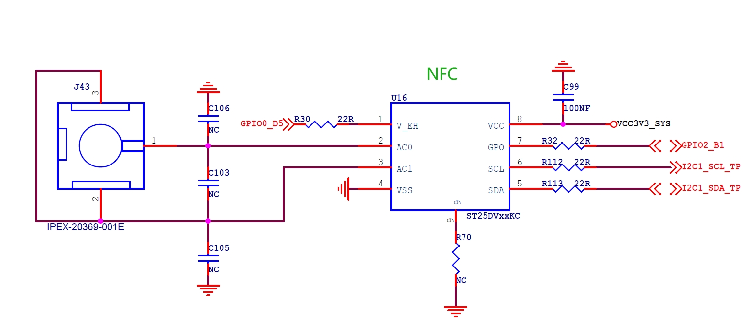
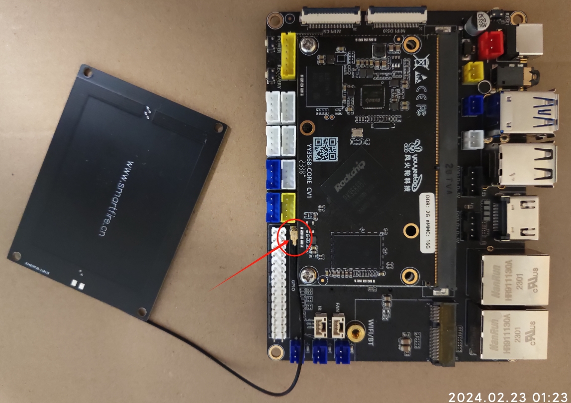
NFC antenna connection diagram:
¶ Experiment on NFC chip driven by I2C communication
To drive NFC, the first firmware version that needs to be refreshed is the version starting from 20240222. If your development board firmware version is newer than this, you don't need to upgrade it

Firmware download link (version here is 20240222):
https://pan.baidu.com/s/1nd8CwWPogZW50uopNN-rHQ?pwd=fkwg
Please refer to the burning system section for firmware flashing:
https://wiki.youyeetoo.com/en/YY3568/unpack
Development board end control NFC corresponding APP
The development board is developed under the Android system and is mainly designed in two layers:
The JNI layer is responsible for I2C low-level communication and GPO interrupt monitoring
The Java layer is responsible for the implementation of various functional logic in ST25DV
The implementation effect of the development board software is shown in the figure:
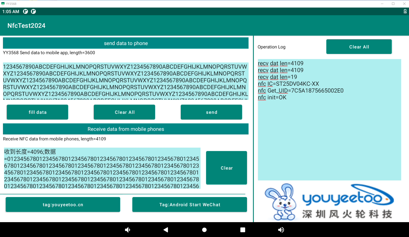
The upper left part of the interface is mainly used to send data from the development board to the mobile phone
Fill data: Fill in test data
Clear All: Clear
Send: The development board sends data to the phone
The lower left part of the interface is mainly used to receive messages from mobile phones
Clear: Clear the data sent by the phone
On the bottom left side of the interface: Write labels
Tag: youyeetoo.cn Write a label for www.youyeetoo.cn
Tag: Android Start WeChat Write tag: Enable the phone to flash the development board antenna and start the WeChat app automatically
On the right side of the interface: is the operation log of the operation section
The FTM data transmission process and protocol between the development board and the mobile phone are as follows:
1 sender -->receiver sends inquiry packets
FE FE FE  FE  FLG1 00 00 00 14 L1 L2 L3 L4 FF FF FF FF 45 4E 44
Among them
FLG1: indicates the direction of data transmission, 02 development board ->mobile, 03: mobile ->development board
L1 L2 L3 L4: Indicates the total length of data to be sent (including all query packet lengths+business data length): The high bit of L1 length, L4 is the lowest bit of length, L2, L3, and so on


2 receiving end -->sending end responds to the response packet
FE FE FE FE 04 00 00 00 00 14 FLG2 00 00 00 00 FF FF FF FF 45 4E 44
among
FLG2: Indicates whether data acceptance is allowed E7 indicates acceptance, while E9 indicates busy refusal
The process of sending data from the sender:
- The sender sends an inquiry packet first, asking if the target can accept the specified length of data
If the target response allows sending, proceed to step 3; otherwise, exit sending - Split and unpack the data and send it until it is complete
The process of receiving data at the receiving end: - Received a query to see if it is possible to accept a specified length packet. If it is allowed to send a reply packet, proceed to step 2. Otherwise, if it is busy, reject the reply packet to the sender and end the acceptance
Wait and receive the data in sequence until the specified length of data is received, and combine it into a complete package
Due to the large amount of code, it will not be displayed here. Please download the source code for viewing and verification
Development board app and source code download:
Compiled APK:
http://dd.youyeetoo.cn:5000/sharing/tGYlp9C1C
Source code:
http://dd.youyeetoo.cn:5000/sharing/prwGLKD2L
Mobile NFC corresponding APP
The mobile app refers to the development library provided by STMicroelectronics for secondary packaging development
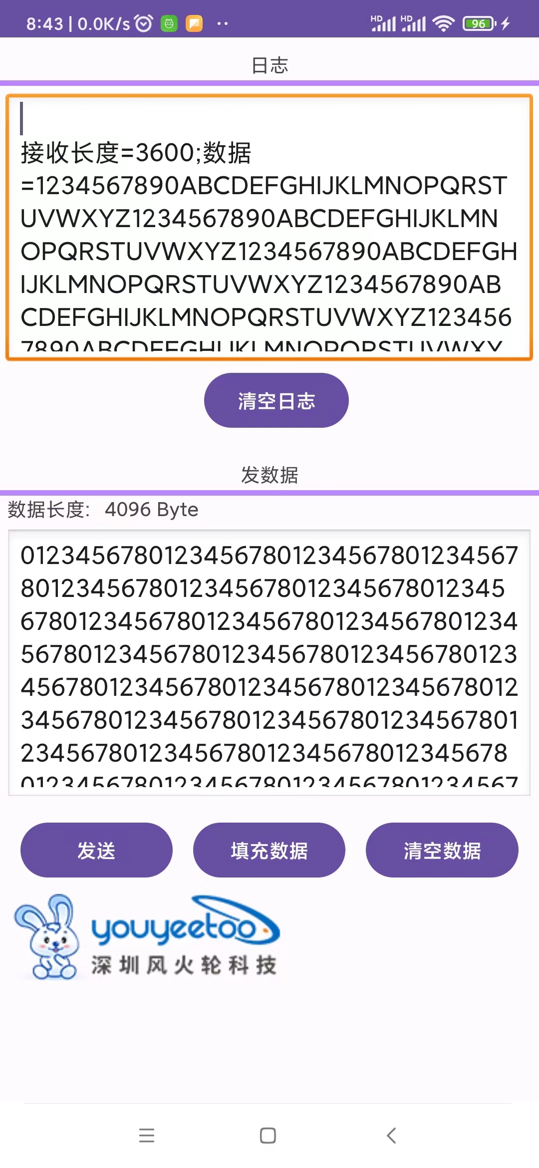
Clear log: Clear the previous part of the log
Send: Send data from the mobile end to the development board
Fill in data: Fill in the data to be sent
Clear data: Clear the data to be sent
The FTM data transmission process and protocol between the development board and the mobile phone are the same as the above development board
Due to the large amount of code, it will not be displayed here. Please download the source code for viewing and verification
Mobile app and source code download:
Compiled APK:
http://dd.youyeetoo.cn:5000/sharing/ALVndNaSa
Source code:
http://dd.youyeetoo.cn:5000/sharing/RBNCwYbIu