¶ GPIO Development(Linux)
1. Hardware Description:
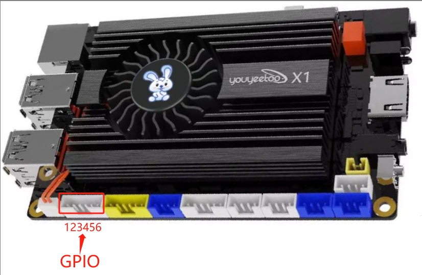
J2306 socket on the motherboard is 5 programmable GPIO, we need to use inpoutx64 library for input and output operations.


| No. | Description | Address of the corresponding operation |
|---|---|---|
| 1 | GPIO-H19 | 0xFD6D0730 |
| 2 | GPIO-H18 | 0xFD6D0720 |
| 2 | GPIO-H18 | 0xFD6D0720 |
| 3 | GPIO-H17 | 0xFD6D0710 |
| 4 | GPIO-H16 | 0xFD6D0700 |
| 5 | GPIO-H00 | 0xFD6D0600 |
| 6 | GND | None |
2.Download testing software (kernel mapping driver mode):
Download the source code of Linux GPIO testing software:
linux-gpio-test-src-File

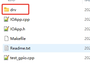
Source code directory structure description:
| File/Folder | Description |
|---|---|
| DRV folder | GPIO kernel mapping driver |
| IOApp. h | gpio application interface header file |
| IOApp. cpp | gpio application interface source file |
| Test_ Gpio. cpp | Test code main |
| Makefile | Make Compilation Script File |
| Readme. txt | Compilation process description file |
The compilation and operation process is as follows. The starting directory is linux-gpio
Before performing the compilation operation, it is necessary to first install the basic compilation tools. Please refer to the instructions in "Linux Application Development (Calling Hardware)" for the installation method.
#Enter the gpio driver source directory
user@X1:~/linux-gpio$  cd  drv

#Compile GPIO driver
user@X1:~/linux-gpio/drv$  make

#Return to the previous level directory
user@X1:~/linux-gpio/drv$  cd  ..

#Copy the driver ko to the current directory
user@X1:~/linux-gpio$  cp  drv/gpio_drv.ko   ./

#Compiling GPIO Test Applications
user@X1:~/linux-gpio$  make

#Execute program program
user@X1:~/linux-gpio$  sudo ./test_gpio
If there are no errors in the above operation, the test results will be displayed as follows:
$ sudo ./test_gpio

GPIO输出成功,LED控制成功,GPIO-H19输入电平:84000102
Special reminder: Because it is controlling hardware, sudo is required to run the test program. If it is a root account, it can be run directly
3. GPIO application interface (kernel mapping driver method) description:
3.1 The following is a description of the structure of the IOApp. h file
#ifndef _IOAPP_H
#define _IOAPP_H

#include <stdint.h>

//5 IO control addresses
#define GPIO_H19_ADR 0xFD6D0730
#define GPIO_H18_ADR 0xFD6D0720
#define GPIO_H17_ADR 0xFD6D0710
#define GPIO_H16_ADR 0xFD6D0700
#define GPIO_H00_ADR 0xFD6D0600

//Before use, it is necessary to dynamically load the driver: Load module method 1: (Only load this module)
//Command Line:  sudo chmod 644  gpio_drv.ko
//Command Line:  sudo insmod gpio_drv.ko
class IOApp
{
    //Drive
    int fd;
public:
    IOApp();
    ~IOApp();

 //Connecting the GPIO kernel driver
    bool Open();

  //Release GPIO kernel driver
    void Release();
public:
    //GPIO output high and low levels
    bool Gpio_Out(uint32_t PhysAddr,bool HightLevel);

    //GPIO input level: If the value is 0X84000102, it indicates high level; if the value is 0X84000100, it indicates low level
    bool Gpio_In(uint32_t PhysAddr,uint32_t *lpVal);

    //Set gpio to output mode
    bool Gpio_SetModel_OutPut(uint32_t PhysAddr);

    //Set gpio as input mode
    bool Gpio_SetModel_InPut(uint32_t PhysAddr);

    //Setting GPIO to interrupt mode has not been implemented yet
    bool Gpio_SetModel_Interrupt(uint32_t PhysAddr);

//The following are LED controls----
//Control the red LED to turn on and off
    bool Led_Ctrl_Red(bool isOn);
 //Control red LED flashing
    bool Led_Ctrl_Red_Flash(bool isOn);

 //Control the green LED to turn on and off
  bool Led_Ctrl_Green(bool isOn);
  //Control green LED flashing
    bool Led_Ctrl_Green_Flash(bool isOn);

};

#endif
3.2 IO Input and Output Description:
3.2.1 The IO port has input mode and output mode
3.2.2 After setting the IO port to output mode, the high and low levels of the output are correct, and the IO values read in this mode are random.
3.2.3 After setting the IO port to input mode, the read value is:
If the reading value is 0X84000102, it indicates high level, and if the value is 0X84000100, it indicates low level
If other values are read out, it is possible that IO is not in input mode.
4. Explanation of other control methods for GPIO (refer to usage based on actual situation):
4.1 GPIO sysfs interface (kernel 4.8 has been disabled by default and is not recommended by the official)
In Linux, the most common way to read and write GPIO is to use the GPIO sysfs interface, which is achieved by operating on files such as export, unexport, gpio {N}/direction, and gpio {N}/value (replacing {N} with actual pin numbers) in the/sys/class/gpio directory. It often appears in shell scripts. Starting with kernel 4.8, support for libgpiod has been added; The original access method based on sysfs will gradually be abandoned.
4.2 Using the libgpiod library to control IO
Libgpiod is a character device interface, and GPIO access control is achieved by manipulating character device files (such as/dev/gpiodchip0). It provides command tools, c libraries, and Python encapsulation through libgpiod.
4.2.1 To use libgpiod, you need to install the libgpiod library on the development board.
#Install the libgpiod library and header files
 sudo apt  -y install libgpiod-dev

#Install the gpiod command-line tool
 sudo apt  -y install gpiod
The above command is installed in version 1.6.3 of libgpiod
4.2.2 Libgpiod control method, the corresponding GPIO numbers on the board are as follows
| Serial number | IO description | libgpiod control IO number |
|---|---|---|
| 1 | GPIO-H19 | 179 |
| 2 | GPIO-H18 | 178 |
| 3 | GPIO-H17 | 177 |
| 4 | GPIO-H16 | 176 |
| 5 | GPIO-H00 | 160 |
4.2.3 gpiod command line control
The commonly used command lines are as follows. You can use - h to view the corresponding instructions for the command
| Command | Function | Usage Example (179 is the GPIO-H19 number) | Description |
|---|---|---|---|
| Gpiodetect | List all GPIO controllers | sudo gpiodetect | List all GPIO controllers |
| Gpioinfo | List the pin situation of the gpio controller | sudo gpioinfo 0 | List the pin group situation of the gpio0 controller |
| Gpioset | Set gpio | sudo gpioset 0 179=0 | Set gpio0 group number 179 pin to low level |
| Gpioget | Get gpio pin status | sudo gpioget 0 179 | Get pin status for gpio0 group number 179 |
| Gpiomon | Monitor the status of gpio | sudo gpiomon 0 179 | Monitor the pin status of gpio0 group number 179 |
4.2.4 Programming and development using libgpiod
The header file corresponding to the libgpiod library is located in/usr/include/gpiod. h
The commonly used functions are as follows:
//Member variables
 struct gpiod_chip;      // GPIO Group Handle
 struct gpiod_line;      // GPIO pin handle

//Obtain GPIO controllers (GPIO groups)
 struct gpiod_chip *gpiod_chip_open(const char *path);

//Obtain GPIO pin
 struct gpiod_line * gpiod_chip_get_line(struct gpiod_chip *chip, unsigned int offset);

//Set pin direction to input mode
 int gpiod_line_request_input(struct gpiod_line *line,const char *consumer);

//Set pins to output mode
 int gpiod_line_request_output(struct gpiod_line *line,const char *consumer, int default_val)

//Set the high and low levels of pins
 int gpiod_line_set_value(struct gpiod_line *line, int value);

 //Read pin status
 int gpiod_line_get_value(struct gpiod_line *line);

//Release GPIO pin
 void gpiod_line_release(struct gpiod_line *line);

//Close the GPIO group handle and release all allocated resources.
 void gpiod_chip_close(struct gpiod_chip *chip);
Simple example: GPIO-H19 outputs high level first, with a delay of 2 seconds, and outputs low level
#Create a gpio-h19. c file
jb@X1:~$ vim  gpio-h19.c
The source code of the gpio-h19.c file is as follows:
#include <gpiod.h>
#include <stdio.h>
#include <unistd.h>
#include <time.h>

int main(void)
{
    const char *chipname="/dev/gpiochip0";
    struct gpiod_line *line_h19;
    int ret;
//Obtain GPIO controller
    struct gpiod_chip *chip = gpiod_chip_open(chipname);

    if (!chip) {
                printf("Open chip by name failed. name: %s\n", chipname);
                return -1;
        }
    //Obtain GPIO-G19 pin
    line_h19 = gpiod_chip_get_line(chip, 179);
        if (!line_h19) {
                printf("Get line failed\n");
                gpiod_chip_close(chip);
                return -2;
        }

    //Set GPIO-G19 to output mode, default output high level
        ret = gpiod_line_request_output(line_h19, "Consumer",GPIOD_LINE_ACTIVE_STATE_HIGH);
        if (ret < 0) {
                printf("Request line_h19 as output failed\n");

                gpiod_line_release(line_h19);
                gpiod_chip_close(chip);
                return -3;
        }
        //Set output status: high level
        ret = gpiod_line_set_value(line_h19, 1);
          if (ret < 0) {
                        printf("Set line_h19 output 1 failed. \n");
                }
        //Delay 2 seconds
        sleep(2);
        //Set output state: low level
         ret = gpiod_line_set_value(line_h19, 0);
          if (ret < 0) {
                        printf("Set line_h19 output 0 failed. \n");
                }
        //Release resources
    gpiod_line_release(line_h19);
    gpiod_chip_close(chip);
    return 0;
}
Compile gpio-h19. c and run it
Note: When compiling, it is necessary to connect to gpiod, and when running, it requires sudo permission or root user
#Compilation
jb@X1:~$ gcc gpio-h19.c -lgpiod

#Run
jb@X1:~$ sudo ./a.out
The above program effect: GPIO-H19 outputs high level first, and then outputs low level after 2 seconds
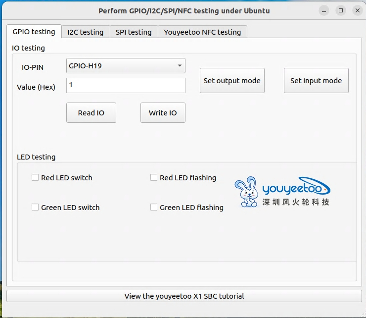
5. GPIO test sample program Qt interface (kernel mapping driver mode):

On the GPIO test page
IO PIO: You can choose to switch between 5 different GIPIOs
Output mode test:
Select the IO to be tested, first click on "Set Output Mode" and set the IO to output mode,
Input 1 (output high level) or 0 (output low level) in the "value (HEX)" position
Then click the "Write IO" button and use a multimeter to measure the corresponding IO to verify if the output level is correct
Input mode test:
Select the IO to be tested, first click on "Set Input Mode" and set the IO to input mode,
The corresponding IO can be connected to GND (low level) or suspended (IO internal pull-up, default high level)
Then click the "Read IO" button to view the read value (if the value is 0X84000102, it indicates high level, and if the value is 0X84000100, it indicates low level) to verify the read result
Please refer to the following page for sample source code and how to compile and use the QT interface of the testing program:
https://wiki.youyeetoo.com/en/x1/linux/qt-build