
中文wiki看这里:
https://wiki.youyeetoo.cn/zh/x1
The youyeetoo X1 is an x86-based single board computer (SBC) launched by youyeetoo.com. It supports full-featured versions of Windows and Linux, which is designed for the AIOT and automation market. With its compact size (115mm * 75mm) and high performance (11th Gen Intel CPU N5105), it offers a range of interfaces commonly used in AIOT applications, including 3x UART, 2x HDMI, 2x USB 3.0, 4x USB 2.0, 1x I2C, 1xSPI, and 5x GPIO. It also supports a 7-inch MIPI touch screen. The recommended model (8GB DDR + 128GB eMMC) is competitively priced at $129, making it an ideal choice for AI edge computing.
¶ Version Difference Table
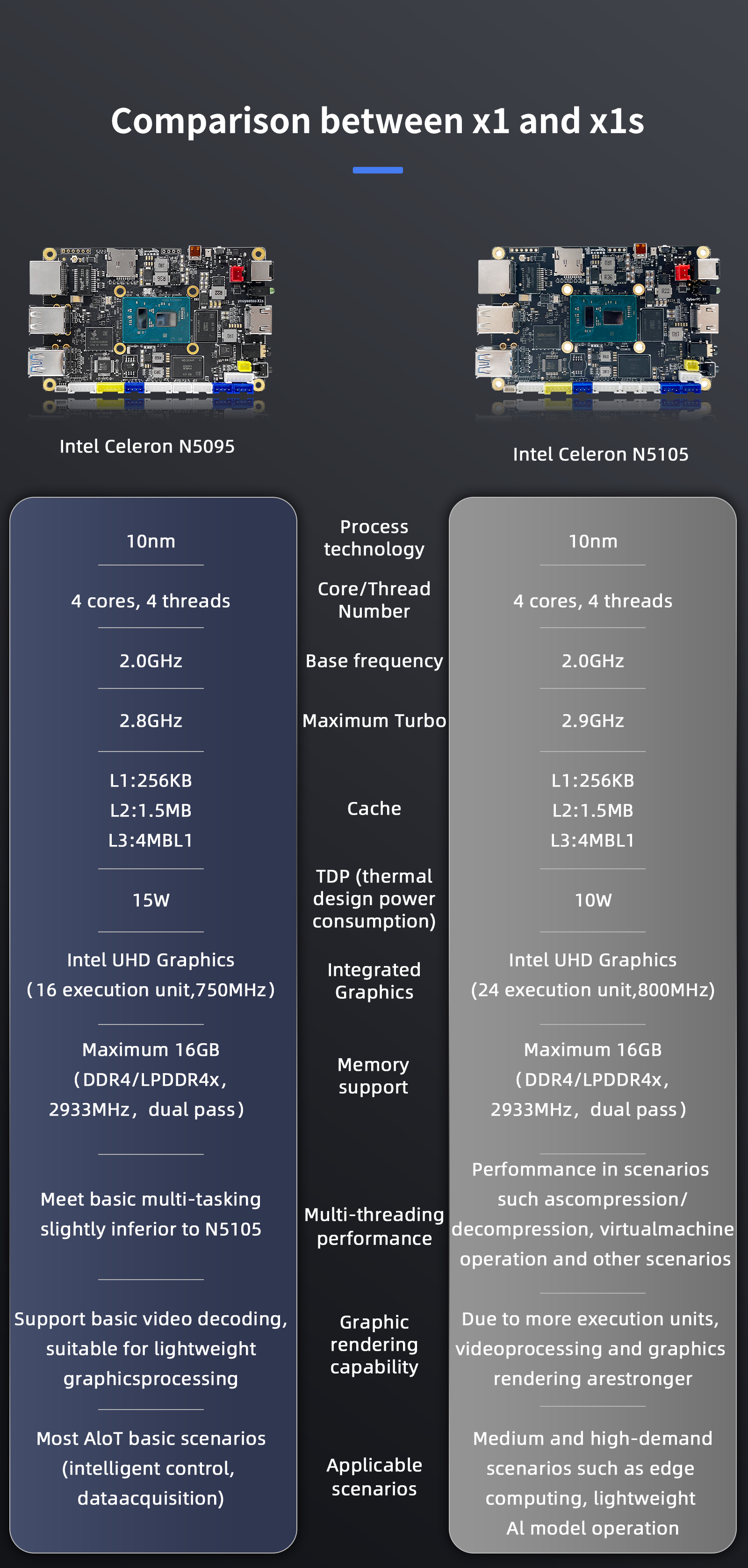
¶ Certification certificate
- certificate CE test report CE certificate FCC test declaration FCC test declaration RoHS Certificate
¶ SPECIFICATIONS
| Item | descriptions |
|---|---|
| CPU: | Intel® Celeron 11'th Gen Jasper Lake N5105 (CPU Frequency: 2.0~2.9GHz,Quad-core 10nm TDP 10W) |
| GPU: | Intel®UHD Core Graphics(Frequency:450 - 800MHz) |
| Memory: | Onboard 4GB / 8GB /16GB LPDDR4 (optional) recommend 8GB |
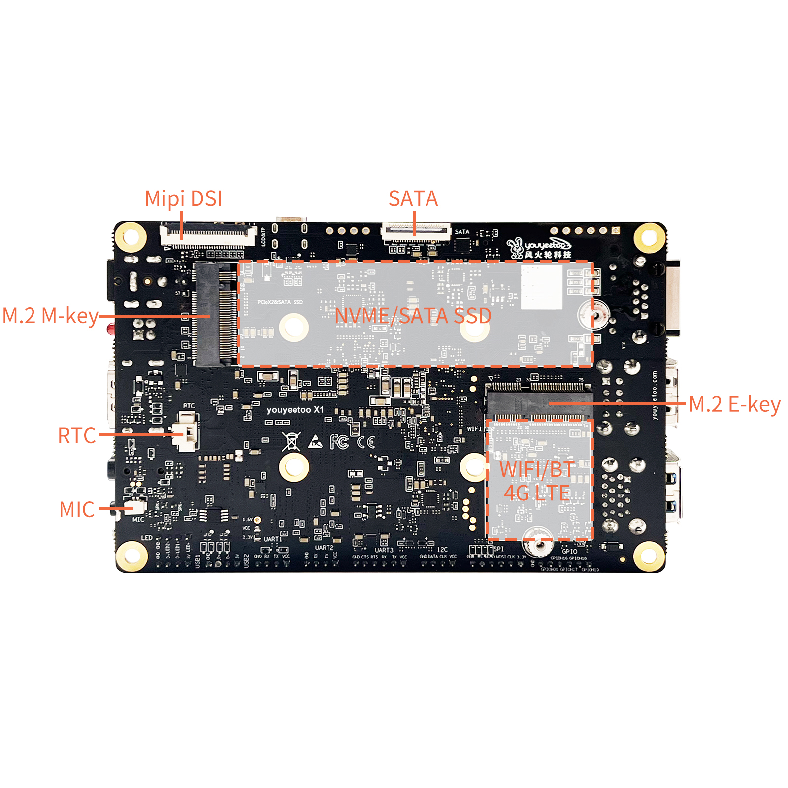
| Storage: | eMMC(V5.1): 0/64G/128G/256G optional M.2 Slots :NVMe 2280 SSD(PCIE3.0) or M.2 SATA 2280 SSD (Support PCle Gen 3.0 x4 lanes NVMe 1.4,compatible with PCle Gen 3.0 x2 NVME) SATA FPC Slots:SATA3 hard disk can be expanded through SATA adapter board(need SATA adapter board) Micro SD(TF) : Supports common SD cards to Extended storage |
| network: | Ethernet: RJ45 Gigabit Ethernet * 1 Wireless: WIFI5+BT5.0 / WIFI6+BT5.2 Expansion via M.2 slot, optional 4G LTE: M.2 E-key slot expansion,4G datamodule such as the EC20/EC25(need 4G adapter board) |
| Display (Multi screen) |
HDMI:HDMI2.0 4K/60Hz Micro HDMI:HDMI2.0 4K/60Hz MIPI FPC :Support Youyeetoo MIPI7LCD(1024 * 600 ) LCD module Multi TOUCH |
| USB | USB-A: USB2.0 * 2 (Limit 1.45A total) Two interfaces share 1.45A USB-A: USB3.0 * 2 (Limit 1.45A total)Two interfaces share 1.45A USB Pin: USB2.0 * 2 (Limit 1.45A total)Two interfaces share 1.45A |
| Audio Output | 3.5 Headphone jack(4line),headset with MIC SPK XH2.0 PIN: Onboard 3W power amplifier,matching 8 ohm speakers HDMI Audio Output (Audio can be output to TV via HDMI) |
| Audio Input | 1. Onboard digital microphone MIC:with noise reduction function(default) 2. Analong MIC: SH0.8mm 2PIN head on the back, 3.3V analog microphone (Switch MIC lnput needs to replace BlOS) |
| M.2 Socket | M.2 M Key: NVME SSD/M.2 SATA SSD (M-key) 2280 M.2 E Key: WIF15+BT5.0/WIFI6+BT5.2 Module 2230 or 4G adapter board to support 4G LTE module (E-key) |
| UART | UART TTL * 3 serial port, XH2.0, 4PIN, Connect RS232 or RS485 /CAN modules can also be use |
| I2C | IIC * 1 XH2.0 4PIN,Provide windows/linux operation example tutorial Default 3.3V |
| SPI | SPI* 1 XH2.0 5PIN,Provide windows/linux operation example tutorial Default 3.3V |
| GPIO | GPIO * 5 XH2.0 6PIN,Provide windows/linux operation example tutorial Default 3.3V |
| LED light | Onboard LED * 2,Parallel 4PIN pin lead, XH2.0, Default 3.3V (defaultred flashes and green off)(Provide a tutorial API interface to control heartbeat flickering) |
| key | Power key * 1 Reset key * 1(restore BIOS setting) |
| RTC | RTC battery Seat : SH1.25 2PIN CR2032 button battery or other 3.3V battery RTC consumes about 35mAh per year |
| Auto Power-on | Turn on * 1 without pressing the power button(can be set in BIOS) |
| Power | 12V DC socket(5.5*2.5): Recommended power adapter 12V3A or XH2.54 2PIN Power socket |
| Dimension | 115 * 75 mm |
| Heat sink | FAN seat specification:SH1.0 4PIN Default heatsink fan 5V/0.2A power Consumption |
| Multi OS | Windows 10/11Linux ubuntu / Linux Debian |
| NFC | NFC device.data transmission with mobile phones/Card Reader, Compatible with android/lOS phones,youyeetoo wiki provides examples |
| Intel watchdog | Implemented via standard windows API |
| CPU temperature reading | Implemented via standard windows API |
| CPU Fan Speed Adjustment | Implemented via standard windows API Fan speed requlation |
| POE | default Support AC/BT protocol 30W POE module,(Need buy POE module additional) 60W support (need to change the power chip on board) contact us |
¶ Interface
V3:
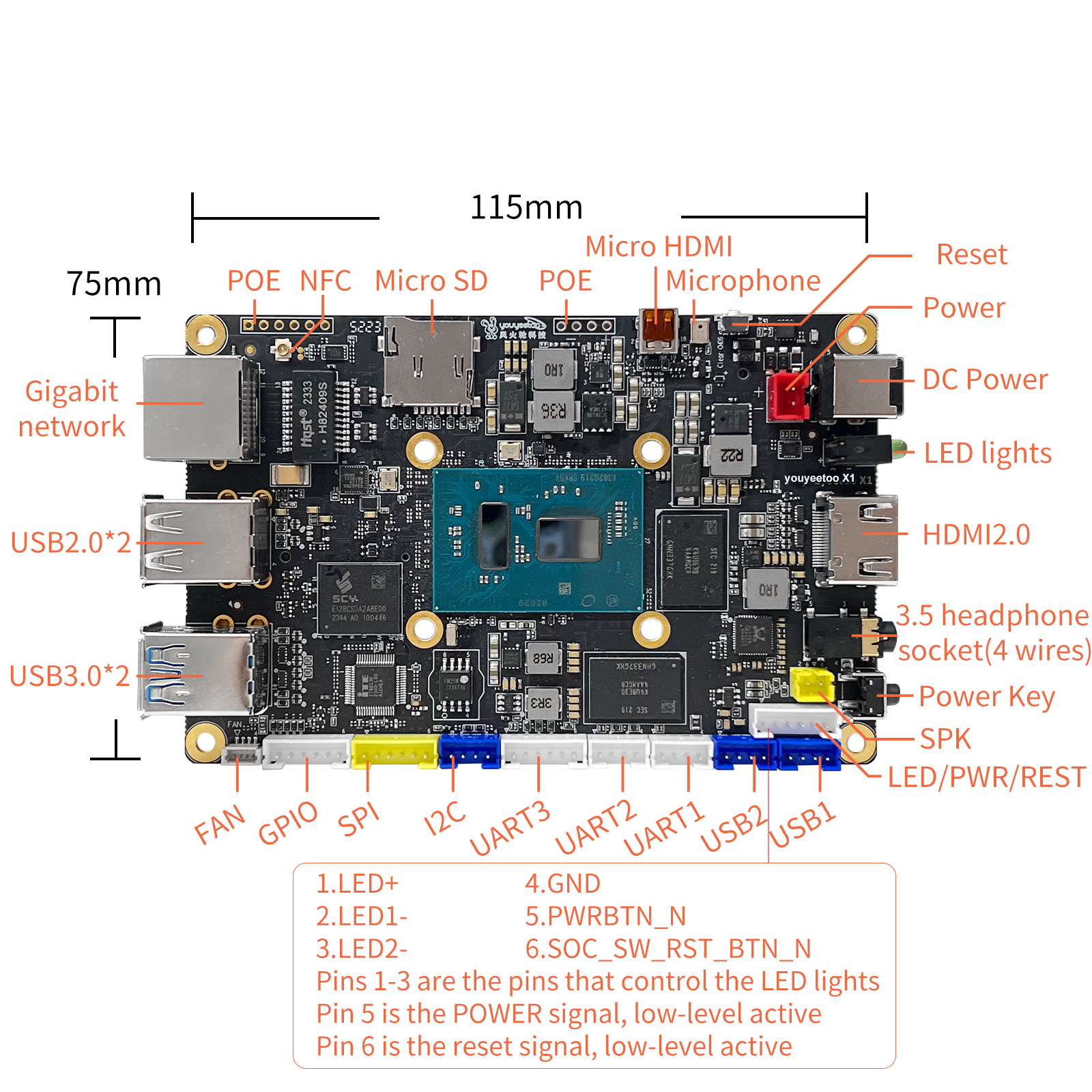
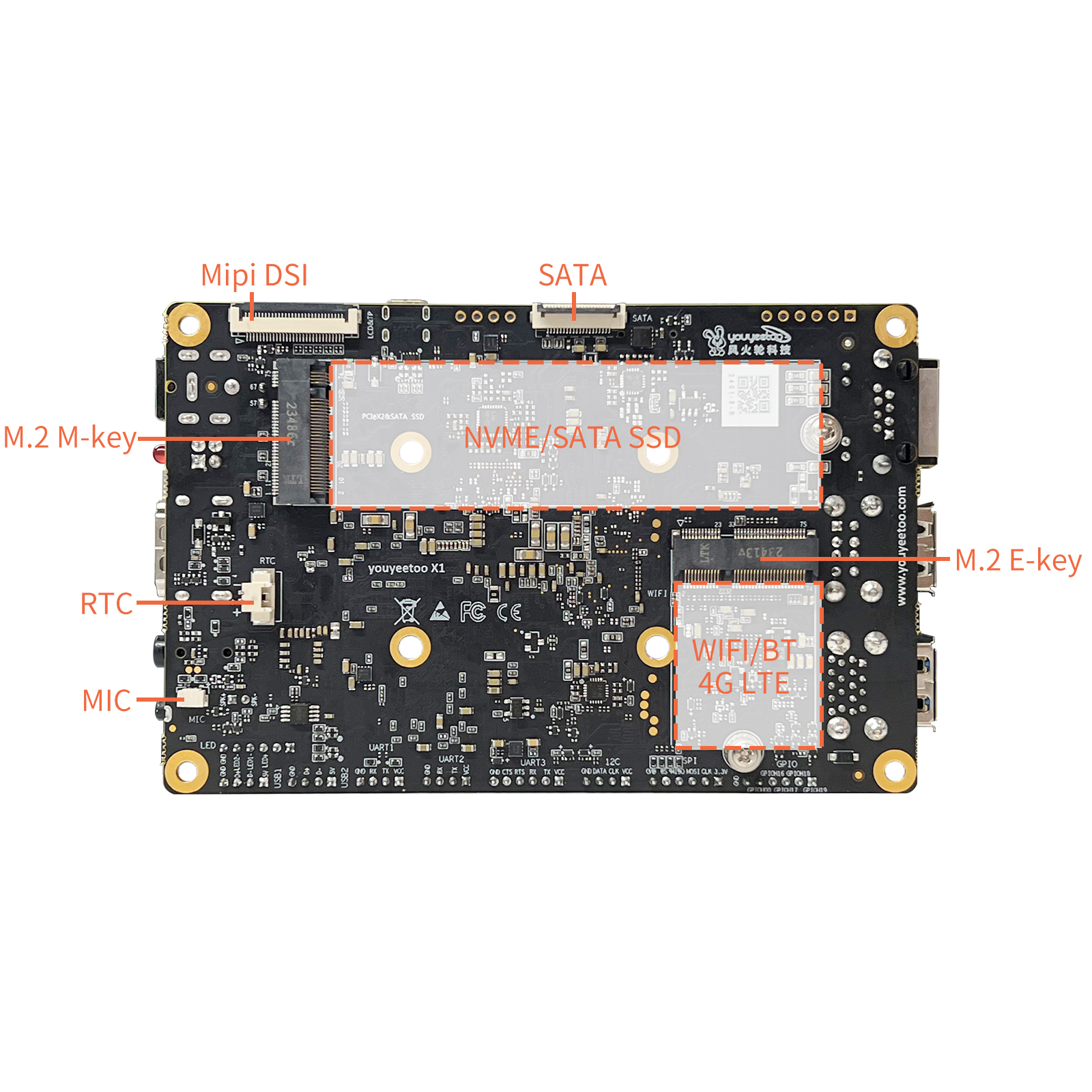
V2:
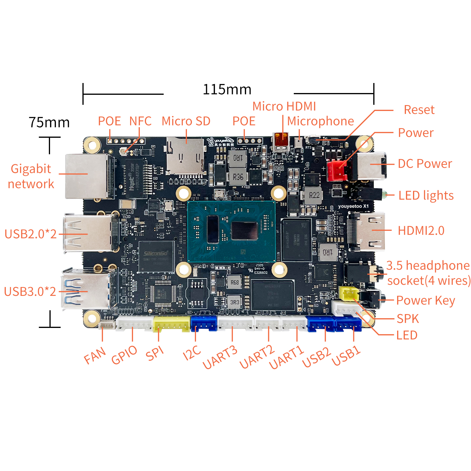
¶ Getting Started Tutorial
¶ Power on and start up
¶ Accessory
- Display screen 10.1HDMI screen 7-inch mipi screen
- Camera usb camera
- NFC NFC antenna
- 4G EC20 4G module
- WIFI/BT RTL8852BE module RTL8822CE module
- POE POE module
- SATA adapter board FPC to SATA adapter board
- Battery RTC battery
- USBI2C USBI2C instructions
¶ Windows
¶ Installation system
¶ Update BIOS
¶ Install the driver
¶ MIPI7LCD display
¶ WIFI/Bluetooth
¶ Camera
¶ 4G LTE
¶ Windows Driver Development
¶ Windows Application Development
This tutorial is an example of how to call the hardware resources on the youyeetoo X1 motherboard in a windows application, to make it easier to control the hardware in real projects.
¶ GPIO Usage
¶ UART serial port Usage
¶ I2C Usage
¶ SPI Usage
¶ NFC Usage
¶ LED Light Control
¶ SPK/Headphone/HDMI Audio Output Switching
¶ MIC input toggle - BIOS change required
¶ Watchdog Usage
¶ Obtain a unique ID identification code
¶ Linux
¶ Installation system
¶ MIPI7LCD display
¶ WIFI/Bluetooth
¶ Camera
¶ 4G LTE
¶ Linux application development (calling hardware)
- This tutorial takes ubuntu-22.04.x-desktop-amd64 as an example, and the basic tools used in application development are installed as follows:
#update soft list
sudo apt-get update

# install make
sudo apt install make
sudo apt -y install make-guile

#install gcc g++
sudo apt  -y install gcc
sudo apt  -y install g++

# install cmake
sudo snap install cmake
sudo apt  -y  install cmake

#install git
sudo apt -y  install git build-essential dkms  --force-yes

#install vim
sudo apt -y install vim

#install curl
sudo apt -y install curl

#install wget
sudo apt -y install wget
- Linux application development, knowledge reserve: Fundamentals of C/C++programming development, foundation of make compilation and Makefile writing
¶ GPIO usage
¶ UART serial port usage
¶ I2C usage
¶ SPI usage
¶ NFC usage
¶ LED light control
¶ SPK/headphone/HDMI audio output switching
¶ MIC input switching - BIOS needs to be changed
¶ Wired network fixed IP/DHCP automatic acquisition of IP
¶ Watchdog usage
¶ Obtain a unique ID identification code
¶ FAQ
¶ Accessory Installation
- Install hard drive NVMe SSD SATA SSD adapter board connected to SATA3 hard drive
- Install WIFI/BT module WIFI5 WIFI6
- POE POE module
- Adjust the fan speed